Philips AN1651 manual IV. Noise Referred to the Input, Guide Lines for Minimizing Noise

Models: AN1651

1 17
Download 17 pages 4.61 Kb
Page 5
Image 5

Philips Semiconductors

Application note


Using the NE/SA5234 amplifier

AN1651


+2.5V


4


±2.5V


11


+


HP


5234


3585


±


SPECTRUM


600Ω

ANALYZER


47k

10Ω

100

x10


SL00634

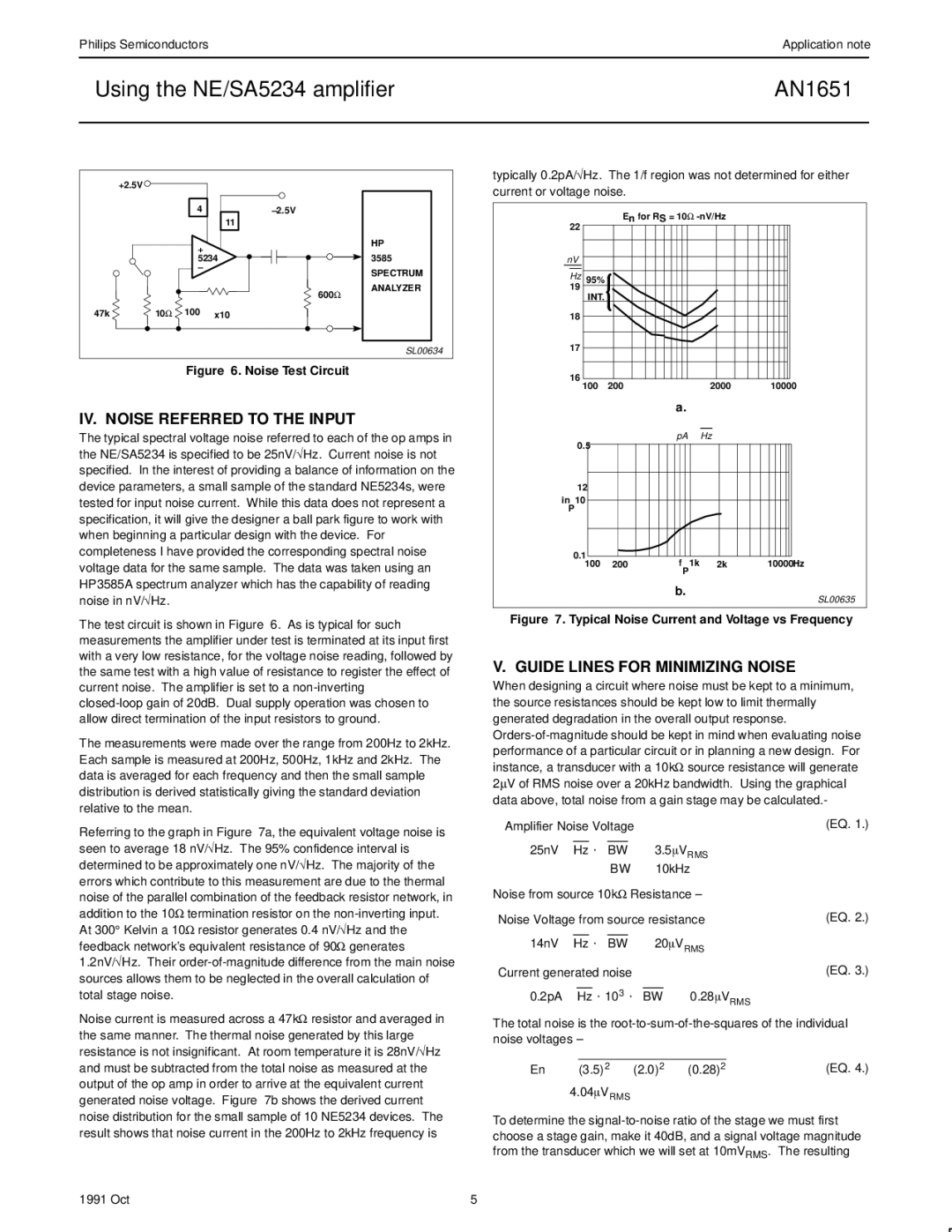
Figure 6. Noise Test Circuit

IV. NOISE REFERRED TO THE INPUT

The typical spectral voltage noise referred to each of the op amps in the NE/SA5234 is specified to be 25nV/Hz. Current noise is not specified. In the interest of providing a balance of information on the device parameters, a small sample of the standard NE5234s, were tested for input noise current. While this data does not represent a specification, it will give the designer a ball park figure to work with when beginning a particular design with the device. For completeness I have provided the corresponding spectral noise voltage data for the same sample. The data was taken using an HP3585A spectrum analyzer which has the capability of reading noise in nV/Hz.

The test circuit is shown in Figure 6. As is typical for such measurements the amplifier under test is terminated at its input first with a very low resistance, for the voltage noise reading, followed by the same test with a high value of resistance to register the effect of current noise. The amplifier is set to a non-inverting

closed-loop gain of 20dB. Dual supply operation was chosen to allow direct termination of the input resistors to ground.

The measurements were made over the range from 200Hz to 2kHz. Each sample is measured at 200Hz, 500Hz, 1kHz and 2kHz. The data is averaged for each frequency and then the small sample distribution is derived statistically giving the standard deviation relative to the mean.

Referring to the graph in Figure 7a, the equivalent voltage noise is seen to average 18 nV/Hz. The 95% confidence interval is determined to be approximately one nV/Hz. The majority of the errors which contribute to this measurement are due to the thermal noise of the parallel combination of the feedback resistor network, in addition to the 10Ω termination resistor on the non-inverting input. At 300° Kelvin a 10Ω resistor generates 0.4 nV/Hz and the feedback network's equivalent resistance of 90Ω generates 1.2nV/Hz. Their order-of-magnitude difference from the main noise sources allows them to be neglected in the overall calculation of total stage noise.

Noise current is measured across a 47kΩ resistor and averaged in the same manner. The thermal noise generated by this large resistance is not insignificant. At room temperature it is 28nV/Hz and must be subtracted from the total noise as measured at the output of the op amp in order to arrive at the equivalent current generated noise voltage. Figure 7b shows the derived current noise distribution for the small sample of 10 NE5234 devices. The result shows that noise current in the 200Hz to 2kHz frequency is

typically 0.2pA/Hz. The 1/f region was not determined for either current or voltage noise.

En for RS = 10Ω -nV/Hz

22

nV

￿Hz 95% 19

INT.

18

17

16

100

200

2000

10000

a.

pA￿ ￿Hz

0.5

12

in 10

P

0.1


100 200

f 1k

2k

10000Hz


P


b.

SL00635

Figure 7. Typical Noise Current and Voltage vs Frequency

V. GUIDE LINES FOR MINIMIZING NOISE

When designing a circuit where noise must be kept to a minimum, the source resistances should be kept low to limit thermally generated degradation in the overall output response. Orders-of-magnitude should be kept in mind when evaluating noise performance of a particular circuit or in planning a new design. For instance, a transducer with a 10kΩ source resistance will generate 2μV of RMS noise over a 20kHz bandwidth. Using the graphical data above, total noise from a gain stage may be calculated.-

Amplifier Noise Voltage


(EQ. 1.)


25nV￿￿Hz @ ￿BW +

3.5VRMS


BW +

10kHz


Noise from source 10kΩ Resistance ±


Noise Voltage from source resistance

(EQ. 2.)


14nV￿￿Hz @ ￿BW +

20VRMS


Current generated noise


(EQ. 3.)

0.2pA￿￿Hz @ 103 @ ￿BW + 0.28VRMS

The total noise is the root-to-sum-of-the-squares of the individual noise voltages ±

En + ￿(3.5)2 ) (2.0)2 ) (0.28)2

(EQ. 4.)

+4.04VRMS

To determine the signal-to-noise ratio of the stage we must first choose a stage gain, make it 40dB, and a signal voltage magnitude from the transducer which we will set at 10mVRMS. The resulting

1991 Oct

5

Page 5
Image 5
Philips AN1651 manual IV. Noise Referred to the Input, Guide Lines for Minimizing Noise

AN1651 specifications

The Philips AN1651 is a highly regarded car audio speaker offering an impressive balance of sound quality and performance. Designed primarily for the car audio enthusiast, this model showcases what modern engineering can achieve in automotive sound systems.

One of the main features of the AN1651 is its dual cone structure that produces clear and rich sound across various frequencies. This design aims to enhance both low and mid-range sounds, ensuring that music is delivered with clarity and precision. Whether you're listening to rock, pop, or classical, the AN1651 is built to convey the nuances of music effectively.

The speaker boasts a peak power handling capability of up to 240 watts, which allows for immersive sound experiences without distortion, even at higher volumes. This capability means that the AN1651 can handle the punchy bass lines typical in many contemporary music genres, making it a popular choice among bass enthusiasts.

Philips also incorporates their innovative technologies, such as a reinforced polypropylene cone. This material enhances sound quality by providing better rigidity while remaining lightweight. The result is a responsive speaker with reduced resonance, contributing to more accurate audio playback. Furthermore, the butyl rubber surround is designed to withstand wear and tear, ensuring durability and longevity in automotive conditions.

The AN1651 also features a sensitivity rating of 91 dB, allowing it to produce powerful sound output even with moderate power input. This feature makes it an ideal choice for vehicles with smaller amplifiers or factory stereo units, as it ensures an enjoyable listening experience without requiring significant upgrades.

In terms of installation, the AN1651 is designed for versatility. Its size makes it compatible with a wide range of vehicles, and the mounting accessories included facilitate an easy and secure fit.

With a smart aesthetic that blends well with various car interiors, the Philips AN1651 speaker is more than just a functional audio component; it is a stylish addition to your vehicle.

In conclusion, the Philips AN1651 combines advanced technologies and thoughtful design to deliver a rich audio experience that car enthusiasts will appreciate. Whether for casual listening or serious audio enjoyment, this speaker meets diverse audio needs, proving to be a valuable investment for any car audio system.