DSR 1000, IT-DSR1000, IT-DSR1000/S specifications
The Philips IT-DSR1000/S, often referred to as the DSR 1000, represents the pinnacle of modern digital satellite receivers, blending advanced technology with user-friendly features. Designed for both home entertainment enthusiasts and casual viewers, the DSR 1000 provides an unparalleled satellite viewing experience that stands out in the market.One of the primary features of the DSR 1000 is its superior image quality, supporting high-definition video formats that provide crystal clear visuals. With up to 1080p resolution, users can enjoy their favorite shows and movies with vibrant colors and stunning detail. This is enhanced by advanced video processing technologies that ensure smooth playback without artifacts, making every viewing session immersive.
The DSR 1000 incorporates a robust and intuitive user interface, enabling viewers to navigate channels and settings effortlessly. A customizable electronic program guide (EPG) allows users to access information about upcoming shows and events, facilitating better viewing choices. The receiver also supports multiple languages, catering to a diverse audience around the globe.
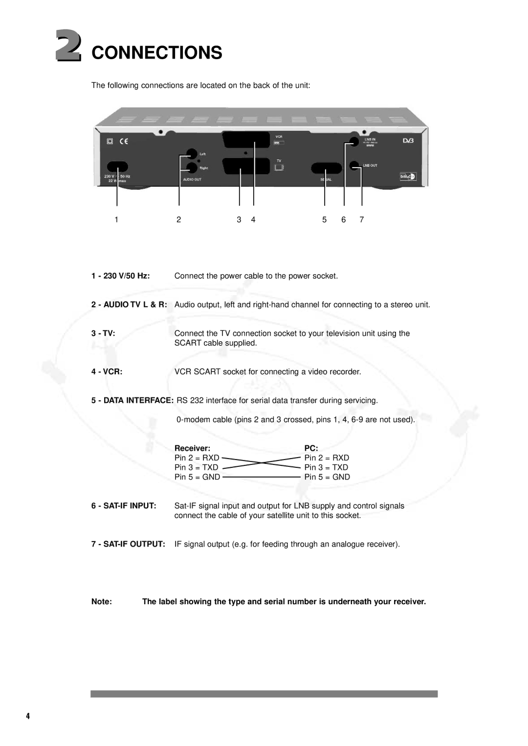
Connectivity is a key characteristic of the DSR 1000. It features multiple HDMI outputs for seamless connection to modern televisions, along with composite and component outputs for older models. Additionally, it includes USB ports for recording live television and downloading content, expanding its functionality.
The Philips IT-DSR1000 is equipped with advanced satellite tuning technologies, ensuring quick and efficient channel scanning and tuning. This feature allows users to quickly find available channels and enjoy their programming without delays. The receiver is also compatible with various satellite formats, making it a versatile choice for different satellite systems.
Audible features are not overlooked, as the DSR 1000 includes digital audio output options, allowing for high-fidelity sound transmitted to audio systems or soundbars. This enhances the overall viewing experience, providing rich and immersive audio quality alongside the stunning visuals.
Overall, the Philips DSR 1000 combines advanced technology, user-friendly features, and exceptional audio-visual performance. Designed for versatility and ease of use, it caters to the needs of various viewers, from dedicated cinephiles to family entertainment seekers. With its commitment to quality and innovation, the DSR 1000 continues to set a high standard in the realm of digital satellite receivers.

