Quicki Use and Setup Guidei | HDTV Monitor |
|
CONTENTS |
|
Important Notice/Warning | . .1 |
Making Basic TV Connections | |
Operating the Television and Remote Control | |
Using the Installation Features | |
Using the | |
Adjusting the Manual Converge Controls | . .8 |
As an Energy Star® Partner, Philips Consumer Electronics has determined this product meets the Energy Star® guidelines for energy efficiency. Energy Star® is a U.S. registered mark. Using products with the Energy Star® label can save energy. Saving energy reduces air pollution and lowers utility bills.
IMPORTANT
This owner's manual is used with several differ- ent television models. Not all features (and draw- ings) discussed in this manual will necessarily match those found with your television set. This is normal and does not require that you contact your dealer or request service.
WARNING: TO PREVENT FIRE OR SHOCK HAZARD DO NOT EXPOSE THIS UNIT TO RAIN OR EXCESSIVE MOISTURE.
MAKING BASIC TV CONNECTIONS
BEST VIEWING
The major benefit of this projection television is its large view-
ing screen. To see this large screen at its best, test various locations in the room to find the optimal spot for viewing.
NOTE: Be sure to allow a free flow of air to and from the per- forated back cover of the set.
To avoid cabinet warping, cabinet color changes, and increased chance of set failure, do not place the TV where temperatures can become excessively
Magnetic fields, such as those of external speak- ers, may cause the picture to distort if the speak- ers are placed too close to the television. Move the magnetic field source away from the TV until there is no picture distortion.
CABLES AND CONNECTORS
If you are new to making TV hookups, you may want to read this section. (The cables and connectors discussed are not sup-
plied with your set. You can buy them at most stores that sell audio or video products. Or call our Customer Care Center at
This publication provides you with examples of basic connections. See pages
A
A
A 300- to
Video and audio cables with standard RCA (phono) connectors con- nect the video and audio jacks of accessory devices such as VCRs and DVD players to the jacks on the TV.
To simplify making connections, the connectors are usually color coded. The jacks on your TV are likewise color coded to match the colors of the connectors. The coding is as follows: yellow for video (composite) and red and white for the right and left audio channels, respectively. Use an audio cable with a white connector when making mono,
or nonstereo, connections. The connectors of video cables used to connect component video or RGB
An
formance than regular (com- posite) video connections.
only with
A DB15 cable makes an RGB connection to the HD
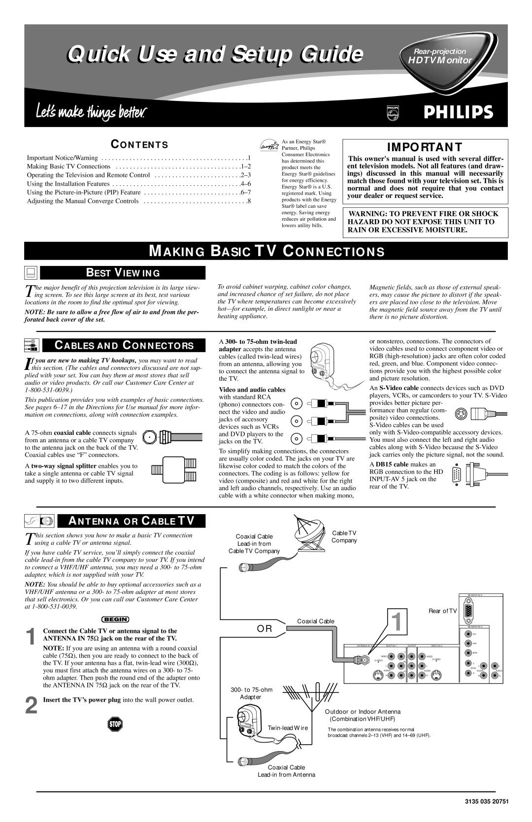
ANTENNA OR CABLE TV
This section shows you how to make a basic TV connection
Coaxial Cable
Cable TV
using a cable TV or antenna signal.
Company
If you have cable TV service, you’ll simply connect the coaxial cable
Cable TV Company
NOTE: You should be able to buy optional accessories such as a VHF/UHF antenna or a 300- to
1 Connect the Cable TV or antenna signal to the ANTENNA IN 75Ω jack on the rear of the TV.
NOTE: If you are using an antenna with a round coaxial cable (75Ω ), then you are ready to connect to the back of the TV. If your antenna has a flat,
2 Insert the TV’s power plug into the wall power outlet.
OR |
| 1 |
| Rear of TV |
|
|
| ||
Coaxial Cable |
|
|
|
|
ANTENNA IN 75Ω | OUTPUT | |||
|
| Y |
|
|
| VIDEO |
|
| VIDEO |
|
|
| ||
| Pb |
| L | |
| L |
|
| |
| L |
|
| L |
| AUDIO | Pr |
| AUDIO |
| R |
|
| R |
300- to
Outdoor or Indoor Antenna
(Combination VHF/UHF)
The combination antenna receives normal | |
| broadcast channels |
HD
HD
G/Y
R/Pr
B/Pb
V
L ![]()
![]() L
L
SYNC
AUDIOAUDIO
H
RR
Coaxial Cable
3135 035 20751