 Blown Air Drying
 Remove the covers from all apertures to allow the escape of
the water-laden air. During drying, air must be able to flow
freely through the generator in order to carry off the moisture.
Direct hot air from two electrical fan heaters of around 1 – 3
kW into the generator air inlet apertures. Ensure the heat
source is at least 300mm away from the windings to avoid
over heating and damage to the insulation.
Apply the heat and plot the insulation value at half hourly
intervals. The process is complete when the parameters
covered in the section entitled, ‘Typical Drying Out Curve’, are
met.
Remove the heaters, replace all covers and re-commission as
appropriate.
If the set is not to be run immediately ensure that the
anticondensation heaters are energised, and retest prior to
running.
Short Circuit Method
NOTE: This process should only be performed by a
competent engineer familiar with safe operating practices
within and around generator sets of the type in question.
Ensure the generator is safe to work on, initiate all mechanical
and electrical safety procedures pertaining to the genset and
the site.
Bolt a short circuit of adequate current carrying capacity,
across the main terminals of the generator. The shorting link
should be capable of taking full load current.
Disconnect the cables from terminals “X” and “XX” of the
AVR.
Connect a variable dc supply to the “X” (positive) and “XX”
(negative) field cables. The dc supply must be able to provide
a current up to 2.0 Amp at 0 - 24 Volts.
Position a suitable ac ammeter to measure the shorting link
current.
Set the dc supply voltage to zero and start the generating set.
Slowly increase the dc voltage to pass current through the
exciter field winding. As the excitation current increases, so
the stator current in the shorting link will increase. This stator
output current level must be monitored, and not allowed to
exceed 80% of the generators rated output current.
After every 30 minutes of this exercise:
Stop the generator and switch off the separate excitation
supply, and measure and record the stator winding IR values,
and plot the results. The resulting graph should be compared
with the classic shaped graph. This drying out procedure is
complete when the parameters covered in the section entitled
'Typical Drying Out Curve' are met.
Once the Insulation Resistance is raised to an acceptable
level - minimum value 1.0 MΩ − the dc supply may be
removed and the exciter field leads “X” and “XX” re-connected
to their terminals on the AVR.
Rebuild the genset, replace all covers and re-commission as
appropriate.
If the set is not to be run immediately ensure that the
anticondensation heaters are energised, and retest the
generator prior to running.
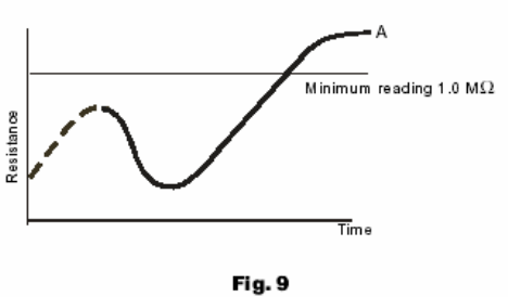
Whichever method is used to dry out the generator the
resistance should be measured every half-hour and a curve
plotted as shown. (fig 6.)
The illustration shows a typical curve for a machine that has
absorbed a considerable amount of moisture. The curve
indicates a temporary increase in resistance, a fall and then a
gradual rise to a steady state. Point ‘A’, the steady state, must
be greater than 1.0 MΩ. (If the windings are only slightly
damp the dotted portion of the curve may not appear).
For general guidance expect that the typical time to reach
point 'A' will be :
1 hour for a BC16/18,
2 hours for a UC22/27
3 hours for an HC4,5,6&7
Drying should be continued after point “A” has been reached
for at least one hour.
It should be noted that as winding temperature increases,
values of insulation resistance may significantly reduce.
Therefore, the reference values for insulation resistance can
only be established with windings at a temperature of
approximately 20°C.
If the IR value remains below 1.0 MΩ, even after the above
drying methods have been properly conducted, then a
Polarisation Index test [PI] should be carried out.
If the minimum value of 1.0 MΩ for all components cannot be
achieved rewinding or refurbishment of the generator will be
necessary.
The generator must not be put into service until the
minimum values can be achieved.
Important ! The short circuit must not be applied with
the AVR connected in circuit. Current in
excess of the rated generator current will
cause damage to the windings.
After drying out, the insulation resistances should be
rechecked to verify minimum resistances quoted above are
achieved.
On re-testing it is recommended that the main stator
insulation resistance is checked as follows :-
Separate the neutral leads