Installation
Note:
•Before finally installing the unit, connect the wiring temporarily, making sure it is all connect- ed up properly, and the unit and the system work properly.
•Use only the parts included with the unit to ensure proper installation. The use of unauthorized parts can cause malfunctions.
•Consult with your nearest dealer if installation requires the drilling of holes or other modifica- tions of the vehicle.
•Install the unit where it does not get in the dri- ver’s way and cannot injure the passenger if there is a sudden stop, like an emergency stop.
•Do not place the display in a position where it will impede the driver’s visibility or affect the operation of your vehicle’s air bags.
•The semiconductor laser will be damaged if it overheats, so don’t install the unit anywhere hot
— for instance, near a heater outlet.
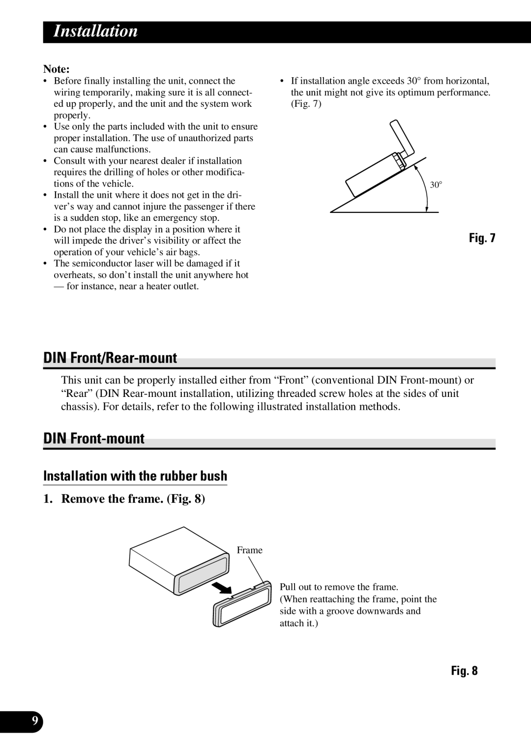
•If installation angle exceeds 30° from horizontal, the unit might not give its optimum performance. (Fig. 7)
30°
Fig. 7
DIN Front/Rear-mount
This unit can be properly installed either from “Front” (conventional DIN
DIN Front-mount
Installation with the rubber bush
1. Remove the frame. (Fig. 8)
Frame
Pull out to remove the frame.
(When reattaching the frame, point the side with a groove downwards and attach it.)
Fig. 8
9