
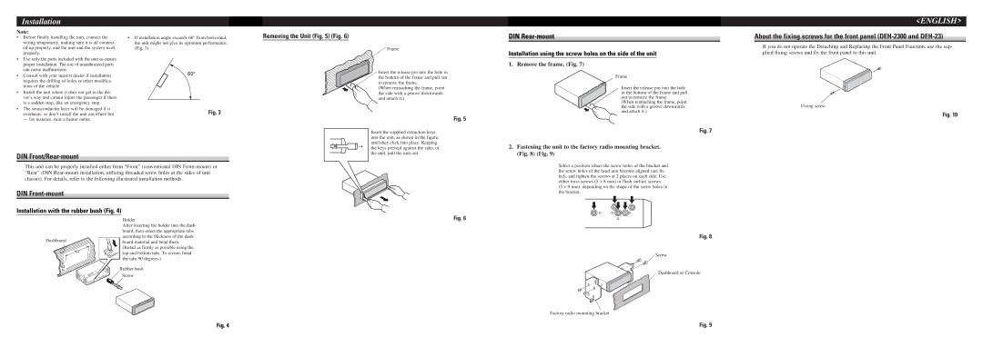
DEH-1300, DEH-2300, DEH-23, DEH-12 specifications
The Pioneer DEH-23, DEH-12, DEH-2300, and DEH-1300 are notable models in Pioneer’s extensive range of CD receivers that cater to a wide variety of audio enthusiasts. These receivers are designed with a blend of user-friendly features, robust audio performance, and versatile connectivity options, making them ideal companions for in-car audio systems.The Pioneer DEH-23 is a compact yet feature-rich receiver known for its sleek design and user interface. One of its standout features is the ability to support various audio formats, including CD, MP3, and WMA playback. The unit comes with advanced sound retriever technology, which enhances the quality of compressed audio files, making them sound closer to their original source. Additionally, it has a built-in equalizer with multiple presets that allow users to customize their audio experience based on their preferences.
Moving on to the DEH-12, this model offers a simplified yet effective blend of features. It retains the core capabilities of CD and MP3 playback while introducing a clean and intuitive display. With its high-power output, the DEH-12 is designed to deliver a punchy audio performance, making it suitable for users who value high volume without compromising on sound quality. It also provides users with basic aux connectivity to easily link their mobile devices to the stereo system.
The DEH-2300 is a more advanced option in this lineup, featuring a USB port and an auxiliary input that allow for seamless integration with various digital devices. This model is known for its enhanced sound quality thanks to the built-in MOSFET amplifier, which delivers greater power efficiency. The DEH-2300 also includes customizable audio settings, such as a 13-band graphic equalizer, providing users with unparalleled control over their audio output.
Lastly, the DEH-1300 rounds out the collection with its combination of classic functionalities and modern enhancements. Similar to the DEH-2300 but with a focus on simplicity, it prioritizes easy navigation and user experience. The receiver features an anti-shock mechanism that prevents audio disruptions during playback, ensuring a smooth listening experience even on rough roads.
In summary, the Pioneer DEH series, including the DEH-23, DEH-12, DEH-2300, and DEH-1300, embodies the brand's dedication to quality sound and user-centric design. Each model brings a unique set of features that cater to different preferences, making them valuable additions to any vehicle's audio system. Whether you are looking for basic features or advanced audio customization, these receivers provide a reliable and enjoyable listening experience.