Connecting the Units
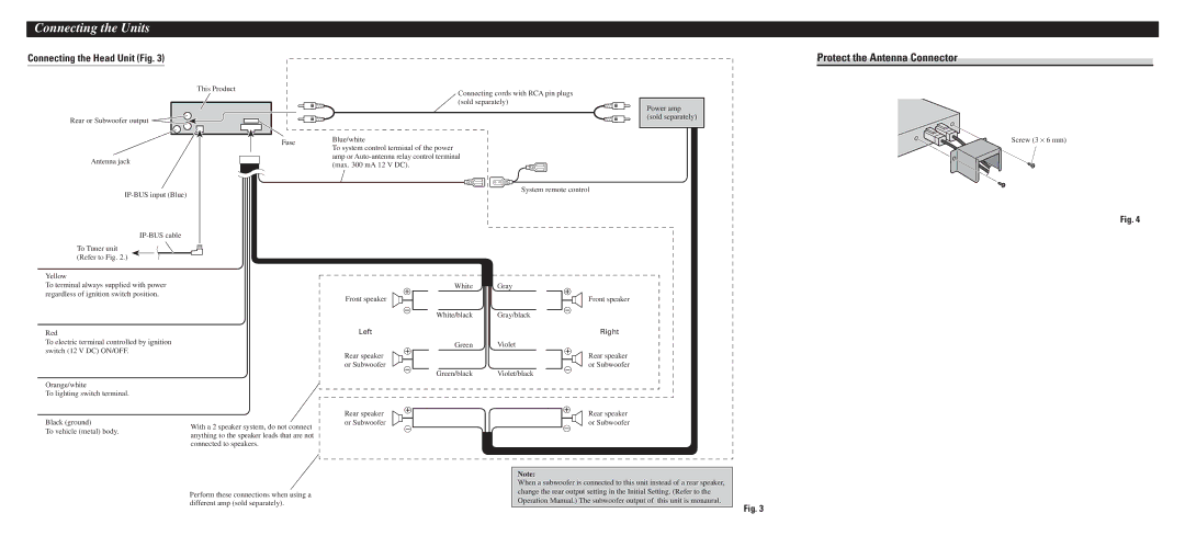
Connecting the Head Unit (Fig. 3)
This Product
Rear or Subwoofer output |
Fuse
Antenna jack
To Tuner unit (Refer to Fig. 2.)
Connecting cords with RCA pin plugs (sold separately)
Blue/white
To system control terminal of the power amp or
System remote control
Power amp (sold separately)
Protect the Antenna Connector
Screw (3 × 6 mm)
Fig. 4
Yellow
To terminal always supplied with power regardless of ignition switch position.
Red
To electric terminal controlled by ignition switch (12 V DC) ON/OFF.
Orange/white
To lighting switch terminal.
White Gray
Front speaker
White/black Gray/black
Left
Green Violet
Rear speaker or Subwoofer
Green/black Violet/black
Front speaker
Right
Rear speaker or Subwoofer
Black (ground)
To vehicle (metal) body.
With a 2 speaker system, do not connect anything to the speaker leads that are not connected to speakers.
Rear speaker |
|
|
|
| Rear speaker | |
or Subwoofer |
|
|
|
|
| or Subwoofer |
|
|
|
| |||
Note:
Perform these connections when using a different amp (sold separately).
When a subwoofer is connected to this unit instead of a rear speaker, change the rear output setting in the Initial Setting. (Refer to the Operation Manual.) The subwoofer output of this unit is monaural.
Fig. 3