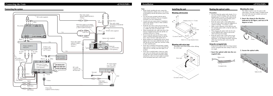
Connecting the Units
Connecting the system
 RCA cable (supplied)
Blue
This product
3 m
<ENGLISH>
Rear video output
(REAR VIDEO OUTPUT) (Yellow)
Left | Right (Red) | |
(White) | Rear audio output | |
Subwoofer output or non fading | ||
(DVD REAR MONITOR | ||
output (SUBWOOFER OUTPUT | OUTPUT) | |
or |
| |
Blue | ||
Right (Red) |
|
Installation
Note:
• Before finally installing the unit, connect the |
wiring temporarily, making sure it is all connect- |
ed up properly, and the unit and the system work |
properly. |
• Use only the parts included with the unit to |
ensure proper installation. The use of unautho- |
rized parts can cause malfunctions. |
• Consult with your nearest dealer if installation |
requires the drilling of holes or other modifica- |
tions of the vehicle. |
• Install the unit where it does not get in the dri- |
ver’s way and cannot injure the passenger if there |
is a sudden stop, like an emergency stop. |
• When mounting this unit, make sure none of the |
leads are trapped between this unit and the sur- |
rounding metalwork or fittings. |
• Do not mount this unit near the heater outlet, |
where it would be affected by heat, or near the |
Installing the unit
Mounting with brackets
Tapping screw (4 ⋅ 12 mm)
Screw
(4 ⋅ 8 mm)
Car mat or chassis | Bracket |
Routing the optical cable
Precaution:
• Try not to bend the optical cable sharply. If it is |
necessary to bend it sharply, make sure that the |
bending radius is at least 25 mm, otherwise the |
cable will not transfer signals properly and so |
this unit will not work properly. |
• Route the optical cable so that nothing heavy |
rests on it, and so that it cannot be stepped on or |
caught in anything – for instance, a door. |
• Make a loop of diameter at least 200 mm with |
the remaining optical cable so that the cable does |
not get strained. |
• When plugging the optical cable into the unit, |
use the supplied cable clamps to prevent the |
cable from being bent sharply. |
• Route the optical cable so that it does not get |
<ENGLISH>
Mounting the clamp
The clamp is used to secure the optical cable when using it. The other clamp is installed on the back side of the head unit similarly and used to secure the optical cable.
1.Insert the clamp in the direction indicated in the figure, and turn it 90 degrees to lock.
BlackBlue
Display with RCA input jacks
3 m
| Left (White) |
| Optical cable (supplied) |
Front video output | Black |
(FRONT VIDEO | |
OUTPUT) |
|
(Yellow) | Head unit |
| (e.g. |
| (sold separately) |
doors, where rainwater might splash onto it. |
• Before drilling any mounting holes always check |
behind where you want to drill the holes. Do not |
drill into the gas line, brake line, electrical wiring |
or other important parts. |
• If this unit is installed in the passenger compart- |
ment, anchor it securely so it does not break free |
while the car is moving, and cause injury or an |
accident. |
Drill 2 to 2.5 mm diameter holes.
Mounting with velcro tape
Thoroughly wipe off the surface before affixing the velcro tape.
caught in moving parts such as the gear shift, |
hand brake, or seat sliding mechanism. Keep the |
cable away from hot spots, such as near the |
heater outlet. |
Using the corrugated tube
To prevent the optical cable from being strained, use the corrugated tube after cutting it to the cor- rect length.
Clamp
To audio ![]() inputs
inputs
RCA cables (sold separately)
![]() To video input
To video input
the TV tuner)
Black | Blue |
3 m
• If this unit is installed under a front seat, make |
sure it does not obstruct seat movement. Route |
all leads and cords carefully around the sliding |
mechanism so they do not get caught or pinched |
in the mechanism and cause a short circuit. |
Velcro tape
•Insert the optical cable into the cor- rugated tube.
Optical cable
2. Secure the optical cable.
|
|
| FM MODULATOR |
|
| (e.g. | |
|
| ||
|
| (sold separately) | |
|
| ||
|
|
| |
| Yellow | Green |
|
|
|
| |
Right (Red) |
|
| |
Left (White) | Yellow | Green |
|
|
|
| |
| Right (Red) |
|
|
|
| 20 pin cable |
|
| Left (White) | (supplied with the display) | |
|
|
| |
RCA cable (supplied with the head unit) ![]()
AV system display (e.g.
Not used.
Red
Video input
(VIDEO INPUT) (Yellow)
Car mat or chassis
Corrugated tube
Optical cable