DEQ-P9 specifications
The Pioneer DEQ-P9 is a high-performance digital signal processor and equalizer that stands out in the realm of automotive audio systems. Designed for audiophiles and car enthusiasts alike, the DEQ-P9 merges cutting-edge technologies with user-friendly features to enhance sound quality and customization within vehicles.One of the main features of the DEQ-P9 is its 31-band graphic equalizer. This allows users to precisely tune the audio output across the entire frequency spectrum. With comprehensive control, users can adjust each band to tailor the sound to their personal preferences or correct for acoustics specific to their vehicle. Coupled with a 5-channel built-in amplifier, the DEQ-P9 ensures that even the most demanding audio setups receive ample power and clarity.
In addition to its equalization capabilities, the DEQ-P9 utilizes advanced time alignment technology. This feature allows users to adjust the audio signal's timing so that all speakers in the vehicle can produce sound coherently. Proper time alignment ensures that sound waves from different speakers reach the listener's ears in perfect synchronization, resulting in clear and immersive audio.
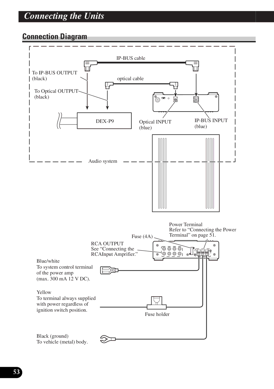
Another hallmark of the DEQ-P9 is its extensive connectivity options, which include digital inputs for both optical and coaxial connections, as well as auxiliary inputs for external devices. This versatility means that various sources of audio can be integrated seamlessly, from traditional CD players to modern smartphones and streaming devices.
The Pioneer DEQ-P9 also supports a variety of sound enhancement technologies, including Dolby Digital and DTS processing. These technologies deliver a cinematic audio experience, enhancing surround sound playback for movie lovers and creating an enveloping atmosphere for music enthusiasts.
Pioneer's commitment to user-friendly design is evident in the DEQ-P9's intuitive interface, which features a full-color display and easy navigation options. This allows users to make quick adjustments on the fly, ensuring that they can enjoy optimal sound quality without distraction.
Moreover, the DEQ-P9 is designed with robust build quality, making it highly reliable for prolonged use. Its compact form factor allows for flexible installation options, fitting comfortably within various vehicle environments.
In summary, the Pioneer DEQ-P9 is an exceptional tool for enhancing the in-car audio experience. With its 31-band graphic equalizer, advanced time alignment, versatile connectivity, and support for immersive sound technologies, it caters to the needs of both casual listeners and dedicated audiophiles. Whether navigating city streets or embarking on long road trips, the DEQ-P9 promises to transform the automotive audio landscape, delivering unparalleled sound quality and customization.

