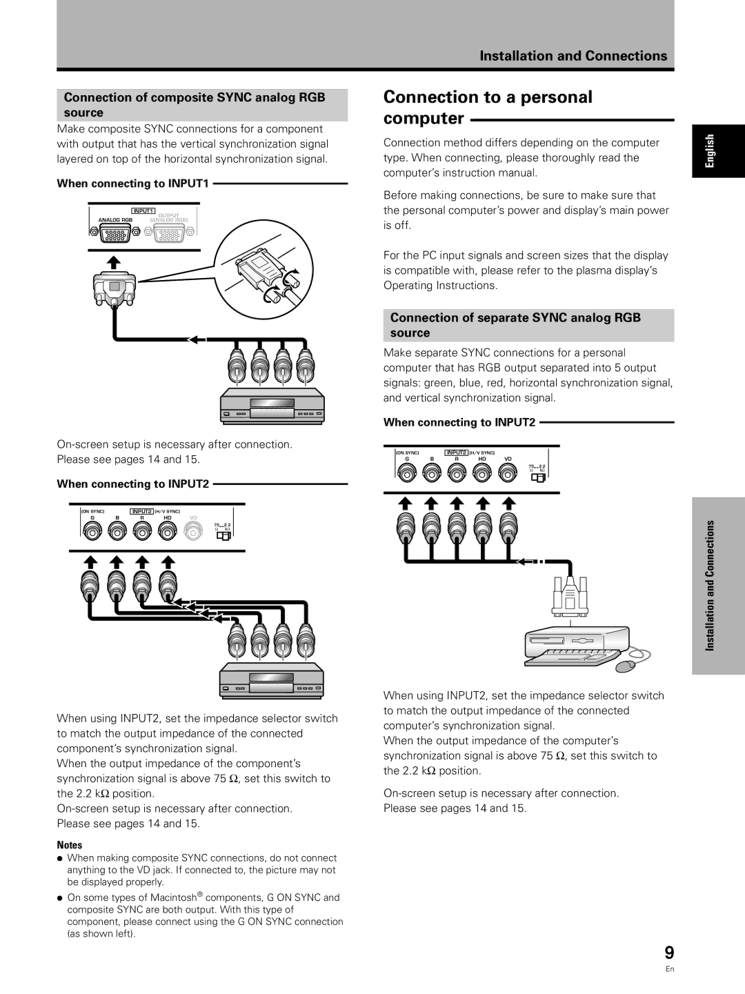
PDA-5002 specifications
The Pioneer PDA-5002 is a hallmark of modern audio technology, designed for enthusiasts who seek high-quality sound and versatile performance in their vehicles. This advanced digital amplifier integrates innovation and functionality to enhance the driving experience, making it a popular choice among car audio aficionados.At the heart of the PDA-5002 is its powerful Class D amplifier architecture. This technology not only provides high efficiency, reducing the load on your vehicle’s electrical system, but it also ensures minimal heat generation, allowing for continuous use without the risk of overheating. With a maximum output power of 500 watts, the PDA-5002 delivers an impressive audio performance, capable of driving multiple speakers while maintaining clarity and dynamic range.
One of the key features of the PDA-5002 is its multi-channel configuration. It includes four channels, allowing users to connect a wide range of speaker setups, from simple front and rear speakers to more complex multi-speaker arrangements. This versatility makes the amplifier ideal for both casual listeners and serious audiophiles who demand high fidelity.
The unit supports a variety of audio signal inputs, including RCA and speaker-level inputs, ensuring compatibility with numerous head units and aftermarket systems. This flexibility is essential for users looking to upgrade their audio without overhauling their entire system.
Pioneer has also incorporated advanced signal processing technologies into the PDA-5002. Features such as adjustable crossover settings allow users to tailor the amplifier’s output to match their specific speakers and personal preferences. Bass boost and high-pass filter settings further enhance the audio experience, enabling users to achieve the perfect sound profile.
Durability is another hallmark of the PDA-5002. Built with robust components and a compact, heat-resistant chassis, it is designed to withstand the rigors of automotive environments, ensuring longevity and reliable performance. Its sleek design allows for easy installation in tight spaces, making it a practical choice for various vehicle models.
In summary, the Pioneer PDA-5002 stands out with its powerful Class D amplification, multi-channel capability, versatile input options, advanced signal processing features, and durable construction. It represents a perfect fusion of innovation and performance, catering to those who seek an enhanced listening experience on the road. For anyone looking to elevate their car audio system, the PDA-5002 is certainly worth considering.

