V8000 specifications
The Pioneer V8000 is a professional-grade digital video and audio player that has gained recognition among DJs, video artists, and event organizers. This versatile device is designed to meet the growing demands of the entertainment industry, offering advanced features and cutting-edge technologies that enhance performances.One of the standout features of the Pioneer V8000 is its support for various media formats. The device can handle multiple file types, including MPEG, AVI, and MP4, making it adaptable to different production requirements. Additionally, it supports a range of resolutions, allowing users to deliver high-quality visuals whether in intimate settings or large-scale events.
Incorporating a robust user interface, the V8000 facilitates seamless navigation. Its intuitive controls give users quick access to essential functions, enabling smooth transitions and effective playlist management. The large LCD screen displays vital information, ensuring that operators can monitor playback closely without disrupting the visual experience.
The V8000 also boasts advanced video effects and transitions, empowering users to create dynamic performances. With support for matrix switching and layering, operators can blend multiple video sources, adding depth and creativity to their work. Furthermore, the device allows the integration of real-time editing and effects processing.
Audio capabilities are equally impressive, as the V8000 is equipped with high-resolution digital audio processing. This ensures that sound quality remains pristine, critical for maintaining the energy and engagement of the audience. The ability to synchronize video and audio outputs also allows for cohesive presentations.
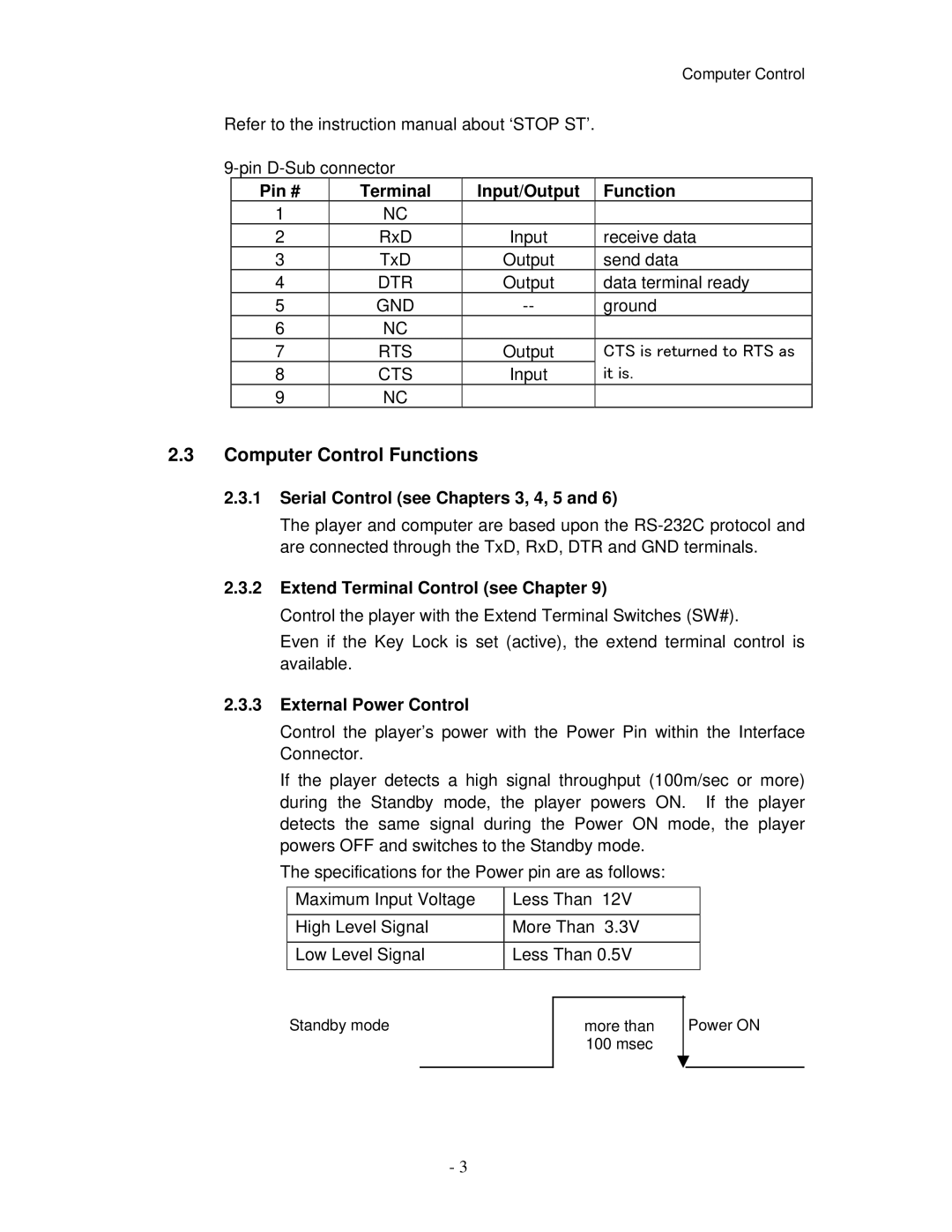
Connectivity is another highlight of the Pioneer V8000. It offers multiple input and output options, including composite, S-Video, and HDMI connectors. This versatility makes it easy to integrate the player into existing setups or connect it directly to projectors, screens, and sound systems.
In terms of build quality, the Pioneer V8000 is designed to withstand the rigors of professional use. Its rugged casing ensures durability while maintaining a lightweight profile that enhances portability. This makes the device suitable for on-the-go professionals who require reliability without compromising on performance.
Overall, the Pioneer V8000 is a powerful tool for professionals in the video and audio industry. With its array of features, user-friendly interface, and robust build quality, it enables users to deliver captivating performances and create memorable experiences for audiences everywhere. The V8000 stands as a testament to Pioneer’s commitment to innovation and excellence in digital media technology.

