MOUNTING THE ATH1 TRANSPORT
1.DO NOT CONNECT POWER TO THE TRANSPORT AT THIS TIME.
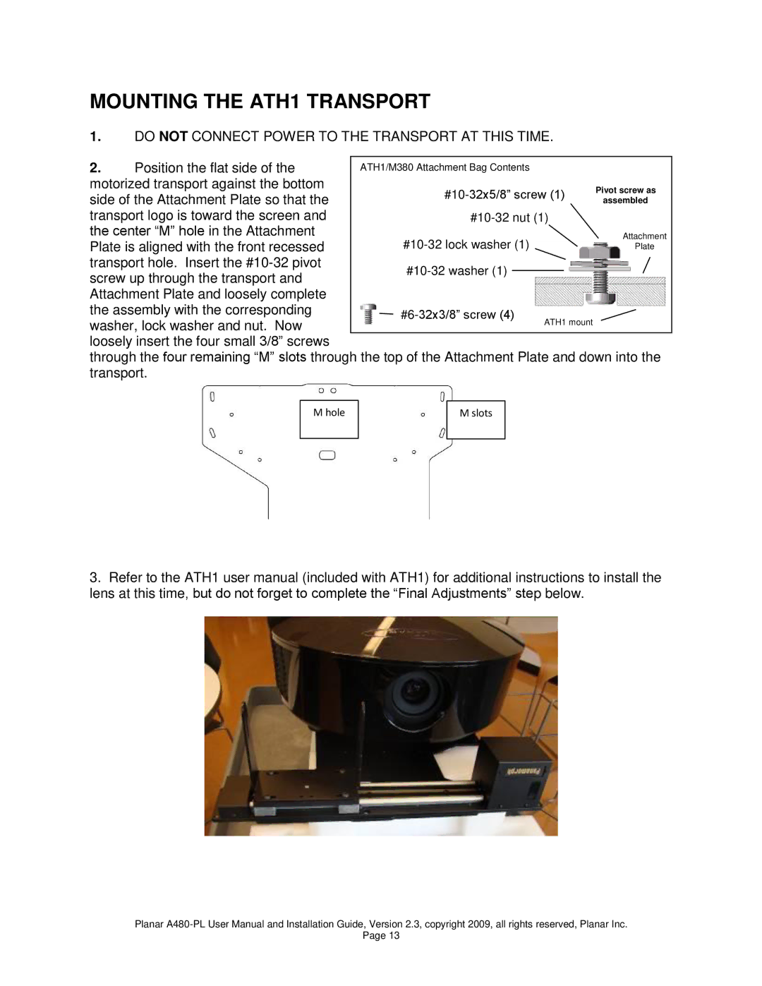
2. | Position the flat side of the | ATH1/M380 Attachment Bag Contents |
|
|
|
|
|
|
|
|
|
| ||||||||
motorized transport against the bottom |
|
|
|
|
|
|
|
|
|
|
|
|
|
|
|
|
|
|
| |
|
|
|
|
|
|
|
|
|
|
|
|
|
| Pivot screw as |
|
| ||||
|
|
|
|
|
|
| ||||||||||||||
side of the Attachment Plate so that the |
|
|
|
|
|
|
| |||||||||||||
|
|
|
|
|
| assembled |
|
| ||||||||||||
|
|
|
|
|
|
|
|
|
|
|
|
|
|
|
|
| ||||
transport logo is toward the screen and |
|
|
|
|
|
|
|
|
|
|
|
|
|
|
|
|
|
|
| |
|
|
|
|
|
|
|
|
|
|
|
|
|
| |||||||
|
|
|
|
|
|
|
|
|
|
|
| |||||||||
the center “M” hole in the Attachment |
|
|
|
|
|
|
|
|
|
|
|
|
|
|
|
|
|
|
| |
|
|
|
|
|
|
|
|
|
|
|
|
|
|
|
| Attachment |
| |||
|
|
|
|
|
|
|
|
|
|
|
|
|
|
|
|
| ||||
|
|
|
|
|
|
| ||||||||||||||
Plate is aligned with the front recessed |
|
|
|
|
|
|
|
|
| Plate |
| |||||||||
|
|
|
|
|
|
|
|
|
|
|
|
|
|
|
|
|
|
| ||
transport hole. Insert the |
|
|
|
|
|
|
|
|
|
|
|
|
|
|
|
|
|
|
| |
|
|
|
|
|
|
|
|
|
|
|
|
|
|
|
|
|
|
| ||
|
|
|
|
|
|
|
|
|
|
|
|
|
|
|
| |||||
screw up through the transport and |
|
|
|
|
|
|
|
|
|
|
|
|
|
|
|
| ||||
|
|
|
|
|
|
|
|
|
|
|
|
|
|
|
|
|
|
| ||
Attachment Plate and loosely complete |
|
|
|
|
|
|
|
|
|
|
|
|
|
|
|
|
|
|
| |
the assembly with the corresponding |
|
|
|
|
|
|
|
|
|
|
|
|
|
|
|
|
|
|
| |
|
|
|
|
|
|
|
|
|
|
|
| |||||||||
washer, lock washer and nut. Now |
|
|
| ATH1 mount |
|
|
|
|
| |||||||||||
|
|
|
|
|
|
|
|
|
|
|
|
|
|
| ||||||
|
|
|
|
|
|
|
|
|
|
|
|
|
|
|
|
|
|
| ||
loosely insert the four small 3/8” screws |
|
|
|
|
|
|
|
|
|
|
|
|
|
|
|
|
|
|
| |
through the four remaining “M” slots through the top of the Attachment Plate and down into the transport.
M hole
M slots
3.Refer to the ATH1 user manual (included with ATH1) for additional instructions to install the lens at this time, but do not forget to complete the “Final Adjustments” step below.
Planar
Page 13