Connector
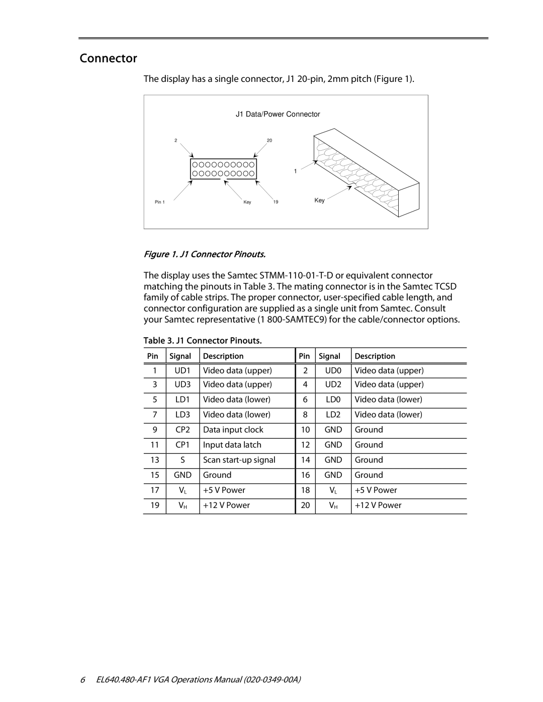
The display has a single connector, J1 20-pin, 2mm pitch (Figure 1).
| J1 Data/Power Connector | ||
2 |
| 20 |
|
|
|
| 1 |
Pin 1 | Key | 19 | Key |
Figure 1. J1 Connector Pinouts.
The display uses the Samtec
Table 3. J1 Connector Pinouts.
Pin | Signal | Description | Pin | Signal | Description |
|
|
|
|
|
|
|
|
|
|
|
|
1 | UD1 | Video data (upper) | 2 | UD0 | Video data (upper) |
|
|
|
|
|
|
3 | UD3 | Video data (upper) | 4 | UD2 | Video data (upper) |
|
|
|
|
|
|
5 | LD1 | Video data (lower) | 6 | LD0 | Video data (lower) |
|
|
|
|
|
|
7 | LD3 | Video data (lower) | 8 | LD2 | Video data (lower) |
|
|
|
|
|
|
9 | CP2 | Data input clock | 10 | GND | Ground |
|
|
|
|
|
|
11 | CP1 | Input data latch | 12 | GND | Ground |
|
|
|
|
|
|
13 | S | Scan | 14 | GND | Ground |
|
|
|
|
|
|
15 | GND | Ground | 16 | GND | Ground |
|
|
|
|
|
|
17 | VL | +5 V Power | 18 | VL | +5 V Power |
|
|
|
|
|
|
19 | VH | +12 V Power | 20 | VH | +12 V Power |
|
|
|
|
|
|
6