5.3.3System Back View
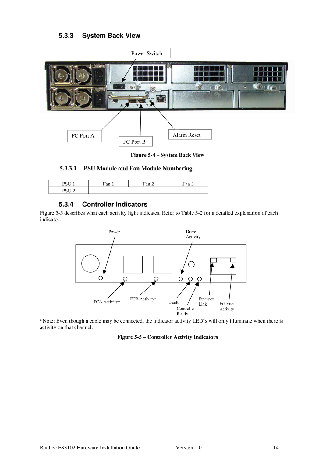
Power Switch
FC Port A
Alarm Reset
FC Port B
Figure 5-4 – System Back View
5.3.3.1PSU Module and Fan Module Numbering
PSU 1 | Fan 1 | Fan 2 | Fan 3 |
PSU 2 |
|
|
|
5.3.4Controller Indicators
Figure 5-5 describes what each activity light indicates. Refer to Table 5-2 for a detailed explanation of each indicator.
Power |
|
|
| Drive | ||||
|
|
|
| Activity | ||||
|
|
|
|
|
|
|
|
|
|
|
|
|
|
|
|
|
|
|
|
|
|
|
|
|
|
|
|
|
|
|
|
|
|
|
|
|
|
|
|
|
|
|
|
|
|
|
|
|
|
|
|
|
|
FCA Activity* | FCB Activity* | Fault | Ethernet | Ethernet |
| Link | |||
|
| Controller | ||
|
|
| Activity | |
|
| Ready |
|
|
*Note: Even though a cable may be connected, the indicator activity LED’s will only illuminate when there is activity on that channel.
Figure 5-5 – Controller Activity Indicators
Raidtec FS3102 Hardware Installation Guide | Version 1.0 | 14 |