POLK AUDIO
Polk Audio was founded in Baltimore in 1972 by Johns Hopkins University graduates Matthew Polk and George Klopfer. Today, Polk Audio is a leading international manufacturer of high quality home, car and multimedia loudspeakers. Polk products emphasize superior sound and build quality, and feature many patented and
1FIGURE 
 OR
OR
FIGURE 1
Most popular placement, above the TV screen. CSi Series Center Speakers are magnetically shielded for safe placement near TV or video monitors. If you notice video distortion or discoloration, immediately move the speakers away from the video source and call Polk Audio Customer Service 800.377.7655 (US and Canada) or polkcs@polkaudio.com.
La ubicación más común es encima de la pantalla del televisor. Los altavoces centrales de la serie CSi tienen blindaje magnético para poder ubicarlos con seguridad cerca de monitores de televisión o de video. Si nota que hay distorsión o descoloración de la imagen, aleje inmediatamente los altavoces de la fuente de video y comuníquese con el servicio al cliente de Polk Audio.
Disposition la plus courante,
Häufigste Platzierung – über dem Fernsehbildschirm.
SAFE LIMITS OF
OPERATION
Your Polk loudspeak- ers are made with the
PLACEMENT RECOMMENDATIONS
FOR THE CSi SERIES CENTER CHANNEL LOUDSPEAKER
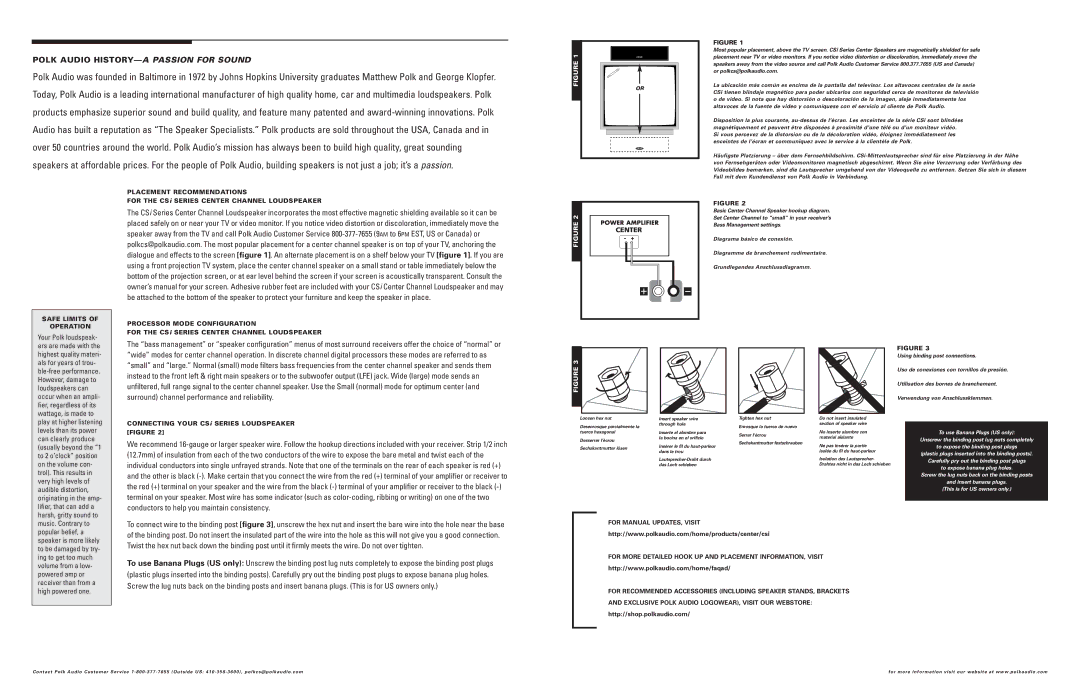
The CSi Series Center Channel Loudspeaker incorporates the most effective magnetic shielding available so it can be placed safely on or near your TV or video monitor. If you notice video distortion or discoloration, immediately move the speaker away from the TV and call Polk Audio Customer Service
PROCESSOR MODE CONFIGURATION
FOR THE CSi SERIES CENTER CHANNEL LOUDSPEAKER
The “bass management” or “speaker configuration” menus of most surround receivers offer the choice of “normal” or
FIGURE 2
FIGURE 2
Basic Center Channel Speaker hookup diagram.
Set Center Channel to “small” in your receiver’s
Bass Management settings.
Diagrama básico de conexión.
Diagramme de branchement rudimentaire.
Grundlegendes Anschlussdiagramm.
FIGURE 3
highest quality materi- als for years of trou-
“wide” modes for center channel operation. In discrete channel digital processors these modes are referred to as “small” and “large.” Normal (small) mode filters bass frequencies from the center channel speaker and sends them instead to the front left & right main speakers or to the subwoofer output (LFE) jack. Wide (large) mode sends an unfiltered, full range signal to the center channel speaker. Use the Small (normal) mode for optimum center (and surround) channel performance and reliability.
CONNECTING YOUR CSi SERIES LOUDSPEAKER [FIGURE 2]
We recommend
FIGURE 3
Loosen hex nut
Desenrosque parcialmente la tuerca hexagonal
Desserrer l’écrou
Sechskantmutter lösen
Insert speaker wire through hole
Inserte el alambre para la bocina en el orificio
Insérer le fil du
|
| Using binding post connections. | |
|
| Uso de conexiones con tornillos de presión. | |
|
| Utilisation des bornes de branchement. | |
|
| Verwendung von Anschlussklemmen. | |
Tighten hex nut | Do not insert insulated |
|
|
Enrosque la tuerca de nuevo | section of speaker wire |
|
|
| To use Banana Plugs (US only): | ||
No inserte alambre con |
| ||
Serrer l’écrou |
| ||
material aislante |
| Unscrew the binding post lug nuts completely | |
|
| ||
Sechskantmutter festschrauben |
|
| |
Ne pas insérer la partie |
| to expose the binding post plugs | |
|
| ||
| isolée du fil du |
| (plastic plugs inserted into the binding posts). |
| Isolation des Lautsprecher- |
| |
|
| Carefully pry out the binding post plugs | |
| Drahtes nicht in das Loch schieben |
| to expose banana plug holes. |
|
|
| |
|
|
| Screw the lug nuts back on the binding posts |
|
|
| and insert banana plugs. |
|
|
| (This is for US owners only.) |
|
|
|
|
music. Contrary to popular belief, a speaker is more likely to be damaged by try- ing to get too much volume from a low- powered amp or receiver than from a high powered one.
To connect wire to the binding post [figure 3], unscrew the hex nut and insert the bare wire into the hole near the base of the binding post. Do not insert the insulated part of the wire into the hole as this will not give you a good connection. Twist the hex nut back down the binding post until it firmly meets the wire. Do not over tighten.
To use Banana Plugs (US only): Unscrew the binding post lug nuts completely to expose the binding post plugs (plastic plugs inserted into the binding posts). Carefully pry out the binding post plugs to expose banana plug holes. Screw the lug nuts back on the binding posts and insert banana plugs. (This is for US owners only.)
FOR MANUAL UPDATES, VISIT
http://www.polkaudio.com/home/products/center/csi
FOR MORE DETAILED HOOK UP AND PLACEMENT INFORMATION, VISIT http://www.polkaudio.com/home/faqad/
FOR RECOMMENDED ACCESSORIES (INCLUDING SPEAKER STANDS, BRACKETS AND EXCLUSIVE POLK AUDIO LOGOWEAR), VISIT OUR WEBSTORE: http://shop.polkaudio.com/
Contact Polk Audio Customer Ser vice | for more information visit our website at www.polkaudio.com |
