OPTION #4
This is the best option to use in stereo or Dolby® Pro Logic® systems with pre- out/main in jacks and small speakers.
Connect the preamp output jacks to the left and right inputs of the PSW650 with high quality RCA cables. Connect the left and right outputs of the PSW650 to the power amp inputs (Figure 9). The L&R outputs of the PSW650 are
FIGURE 9.
AC POWER
The PSW650 has a
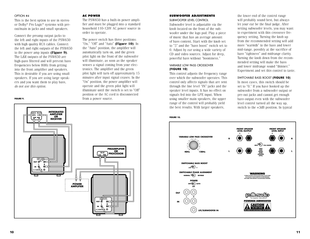
The power switch has three positions: “On,” “Off” and “Auto” (Figure 10). In the “Auto” position, the amplifier will automatically turn on, and the green pilot light on the front of the subwoofer will illuminate, as soon as the speaker senses a signal coming from your elec- tronics. The amplifier and the green pilot light will turn off approximately 15 minutes after input signal ceases. In the “On” position, the power amplifier will operate and the green pilot light will illuminate until the switch is set to “Off” position or the AC cord is disconnected from a power source.
SUBWOOFER ADJUSTMENTS
SUBWOOFER LEVEL CONTROL
Subwoofer level is adjustable via the knob located on the front of the sub- woofer under the logo pod. Play a piece of music that has an average amount of bass content. Start with the knob set to “5” and the “bass boost” switch set to
0.Adjust by ear using a wide variety of CD and video sources. Adjust for deep, powerful bass without “boominess.”
VARIABLE LOW PASS CROSSOVER
(FIGURE 10)
This control adjusts the frequency range over which the subwoofer operates. This control only affects signals that are sent through the line level “IN” jacks and the speaker level inputs. It has no effect on signals fed into the LFE input. When using smaller main speakers, the upper range of the control will probably yield the best results. With larger speakers,
FIGURE 10.
the lower end of the control range will probably sound best, but always let your ear be the final judge. After setting subwoofer levels, you may want to experiment with this crossover fre- quency setting. Turning the knob up from the recommended setting will add more “warmth” to the bass and lower
SWITCHABLE BASS BOOST (FIGURE 10)
In most cases, this switch should be set to “0.” If you have hooked up the subwoofer from a subwoofer output or
10 | 11 |