Manuals
/
Polycom
/
Computer Equipment
/
Mouse
Polycom
MX392
manual
Logic Input
Models:
MX392
1
31
44
44
Download
44 pages
56.9 Kb
28
29
30
31
32
33
34
35
Page 31
Image 31
Page 30
Page 32
Page 31
Image 31
Page 30
Page 32
Contents
Application Note Polycom Installed Voice Business Group
Using the Shure MX392 Push to Talk Microphone with Vortex Devices
Table of Contents
SHURE MX392 BASICS
Switch Behavior
Page
LOGIC PORT
PHYSICAL CONNECTIONS AND GROUNDING
TOGGLE OPERATION PUSH TO TALK
DEFAULT CONDITIONS
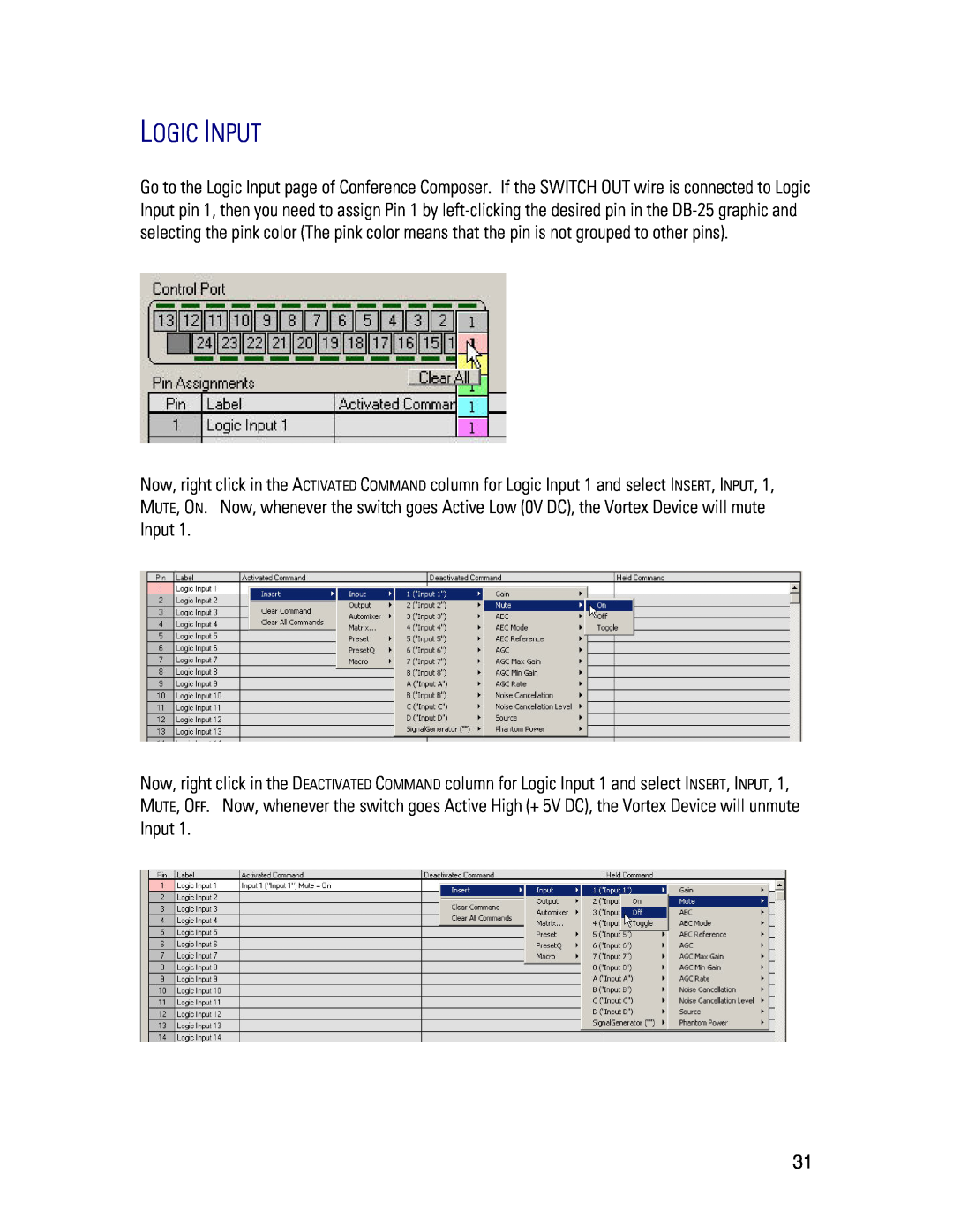
LOGIC INPUT
If you are successful, you should see this on the screen
Do not assign any command to the HELD COMMAND column
LOGIC OUTPUT
Here is what the screen should look like when you are finished
Page
TOGGLE OPERATION PUSH TO MUTE
If you are successful, you should see this on the screen
Do not assign any command to the HELD COMMAND column
LOGIC OUTPUT
Here is what the screen should look like when you are finished
TOGGLE OPERATION MUTE ALL EXAMPLE
Likewise, here is the Macros page for the Vortex EF2241
MACROS
BROADAB01MUTEI11
BROADAF00MUTEI11
Page
LOGIC INPUT
Do not assign any command to the HELD COMMAND column
LOGIC OUTPUT
Page
MOMENTARY OPERATION PUSH TO TALK
LOGIC INPUT
Page
LOGIC OUTPUT
Here is what the screen should look like when you are finished
MOMENTARY OPERATION PUSH TO MUTE
LOGIC INPUT
If you are successful, you should see this on the screen
LOGIC OUTPUT
Here is what the screen should look like when you are finished
MOMENTARY OPERATION MUTE ALL EXAMPLE
Likewise, here is the Macros page for the Vortex EF2241
microphones on all units regardless of whether a microphone is muted from the Vortex EF2280 or the Vortex EF2241. To accomplish this, we will use the BROADA command to send MUTEI commands from one unit to the other unit. The BROADA command broadcasts any command that is after the colon. For example, if a Macro in the Vortex EF2241 has this command
Page
LOGIC INPUT
Page
Page
LOGIC OUTPUT
Make sure the LED works as designed. If you press the membrane switch, you should see the LED above the pins illuminate in Conference Composer as well as on every MX392. Since the switch is a membrane switch, the LED will stay lit until the switch is pushed and held down
Polycom Installed Voice Business Group Contact Information
TECHNICAL SUPPORT
Top
Page
Image
Contents