A
DE
C
B
Fig. 22
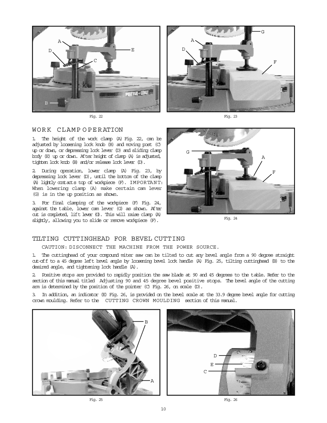
WORK CLAMP OPERATION
1.The height of the work clamp (A) Fig. 22, can be adjusted by loosening lock knob (B) and moving post (C) up or down, or depressing lock lever (D) and sliding clamp body (E) up or down. After height of clamp (A) is adjusted, tighten lock knob (B) and/or release lock lever (D).
2.During operation, lower clamp (A) Fig. 23, by depressing lock lever (D), until the bottom of the clamp
(A) lightly contacts top of workpiece (F). IMPORTANT: When lowering clamp (A) make certain cam lever
(G) is in the up position as shown.
3.For final clamping of the workpiece (F) Fig. 24, against the table, lower cam lever (G) as shown. After cut is completed, lift lever (G). This will raise clamp (A) slightly, allowing you to slide or remove workpiece (F).
G
A
D
F
Fig. 23
G
A
F
Fig. 24
TILTING CUTTINGHEAD FOR BEVEL CUTTING
CAUTION: DISCONNECT THE MACHINE FROM THE POWER SOURCE.
1.The cuttinghead of your compound miter saw can be tilted to cut any bevel angle from a 90 degree straight
2.Positive stops are provided to rapidly position the saw blade at 90 and 45 degrees to the table. Refer to the
section of this manual titled Adjusting 90 and 45 degree bevel positive stops. The bevel angle of the cutting arm is determined by the position of the pointer (C) Fig. 26, on scale (D).
3. In addition, an indicator (E) Fig. 26, is provided on the bevel scale at the 33.9 degree bevel angle for cutting crown moulding. Refer to the CUTTING CROWN MOULDING section of this manual.
B
A
D
E
C
Fig. 25 | Fig. 26 |
10