ASSEMBLY
NOTE: This tool is shipped completely assembled. No assembly time or tools are required.
| 3 |
| 5 |
| 2 |
1 | 4 |
|
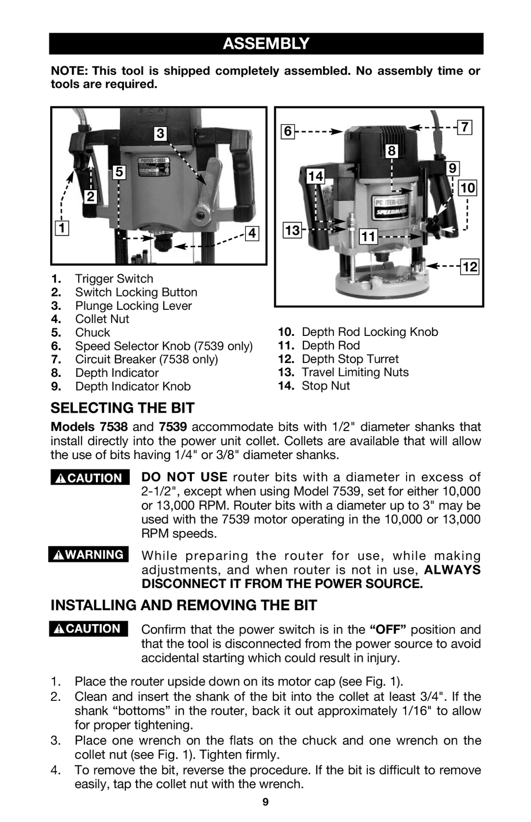
1.Trigger Switch
2.Switch Locking Button
3.Plunge Locking Lever
4.Collet Nut
5.Chuck
6.Speed Selector Knob (7539 only)
7.Circuit Breaker (7538 only)
8.Depth Indicator
9.Depth Indicator Knob
6 | 7 |
|
| 8 | |
14 | 9 | |
10 | ||
|
13![]()
![]()
![]() 11
11![]()
![]()
![]()
![]() 12
12
10.Depth Rod Locking Knob
11.Depth Rod
12.Depth Stop Turret
13.Travel Limiting Nuts
14.Stop Nut
SELECTING THE BIT
Models 7538 and 7539 accommodate bits with 1/2" diameter shanks that install directly into the power unit collet. Collets are available that will allow the use of bits having 1/4" or 3/8" diameter shanks.
DO NOT USE router bits with a diameter in excess of
While preparing the router for use, while making adjustments, and when router is not in use, ALWAYS
DISCONNECT IT FROM THE POWER SOURCE.
INSTALLING AND REMOVING THE BIT
Confirm that the power switch is in the “OFF” position and that the tool is disconnected from the power source to avoid accidental starting which could result in injury.
1.Place the router upside down on its motor cap (see Fig. 1).
2.Clean and insert the shank of the bit into the collet at least 3/4". If the shank “bottoms” in the router, back it out approximately 1/16" to allow for proper tightening.
3.Place one wrench on the flats on the chuck and one wrench on the collet nut (see Fig. 1). Tighten firmly.
4.To remove the bit, reverse the procedure. If the bit is difficult to remove easily, tap the collet nut with the wrench.
9