Instruction Manual
Manuel d’Utilisation
Manual de Instrucciones
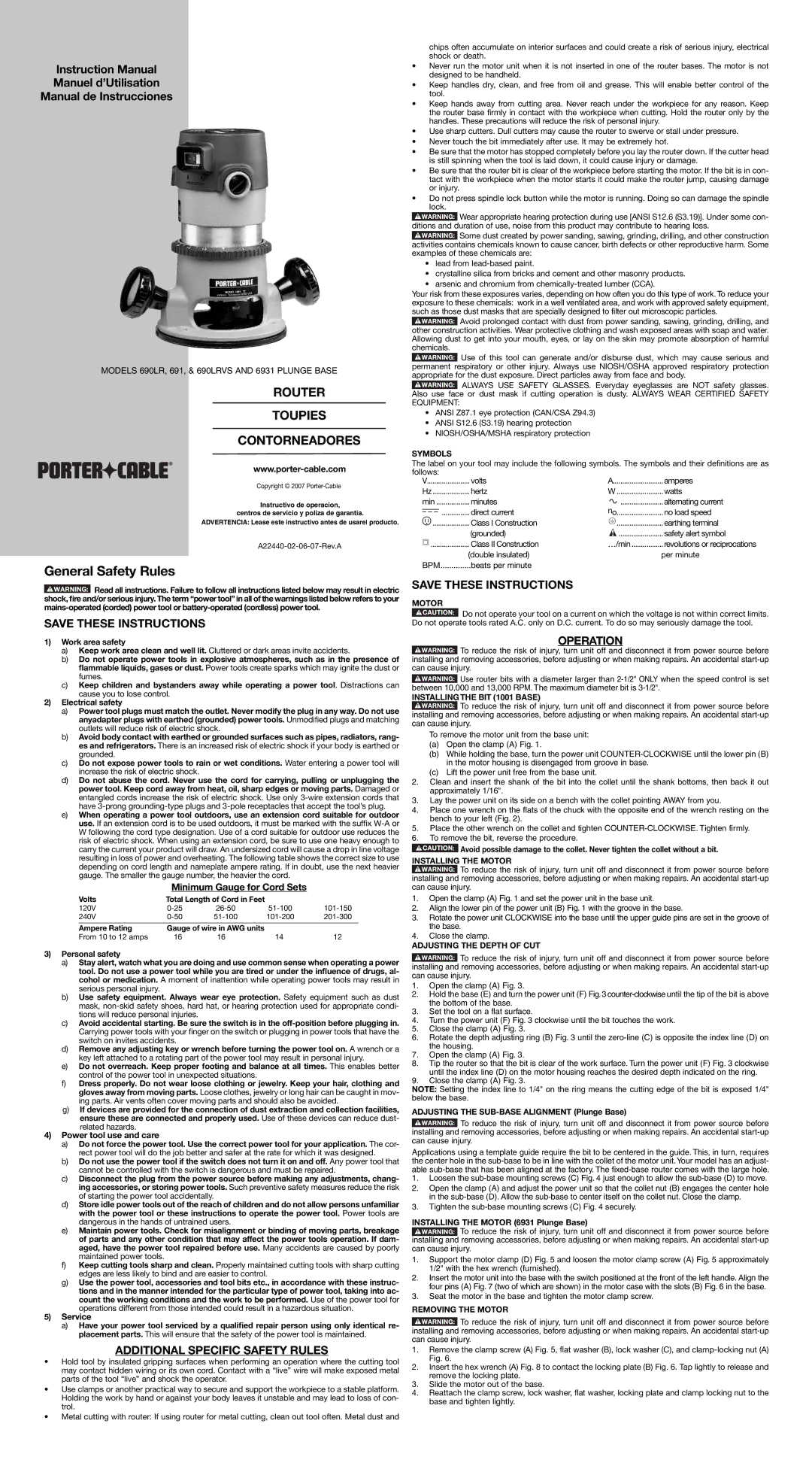
MODELS 690LR, 691, & 690LRVS AND 6931 PLUNGE BASE
ROUTER
TOUPIES
CONTORNEADORES
®
Copyright © 2007
Instructivo de operacion,
centros de servicio y poliza de garantia.
ADVERTENCIA: Lease este instructivo antes de usarel producto.
General Safety Rules
![]() Read all instructions. Failure to follow all instructions listed below may result in electric shock, fire and/or serious injury. The term “power tool” in all of the warnings listed below refers to your
Read all instructions. Failure to follow all instructions listed below may result in electric shock, fire and/or serious injury. The term “power tool” in all of the warnings listed below refers to your
SAVE THESE INSTRUCTIONS
1)Work area safety
a)Keep work area clean and well lit. Cluttered or dark areas invite accidents.
b)Do not operate power tools in explosive atmospheres, such as in the presence of flammable liquids, gases or dust. Power tools create sparks which may ignite the dust or fumes.
c)Keep children and bystanders away while operating a power tool. Distractions can cause you to lose control.
2)Electrical safety
a)Power tool plugs must match the outlet. Never modify the plug in any way. Do not use anyadapter plugs with earthed (grounded) power tools. Unmodified plugs and matching outlets will reduce risk of electric shock.
b)Avoid body contact with earthed or grounded surfaces such as pipes, radiators, rang- es and refrigerators. There is an increased risk of electric shock if your body is earthed or grounded.
c)Do not expose power tools to rain or wet conditions. Water entering a power tool will increase the risk of electric shock.
d)Do not abuse the cord. Never use the cord for carrying, pulling or unplugging the power tool. Keep cord away from heat, oil, sharp edges or moving parts. Damaged or entangled cords increase the risk of electric shock. Use only
e)When operating a power tool outdoors, use an extension cord suitable for outdoor use. If an extension cord is to be used outdoors, it must be marked with the suffix
Minimum Gauge for Cord Sets
Volts | Total Length of Cord in Feet |
|
| |
120V | ||||
240V | ||||
|
|
|
| |
Ampere Rating | Gauge of wire in AWG units |
|
| |
From 10 to 12 amps | 16 | 16 | 14 | 12 |
3)Personal safety
a)Stay alert, watch what you are doing and use common sense when operating a power tool. Do not use a power tool while you are tired or under the influence of drugs, al- cohol or medication. A moment of inattention while operating power tools may result in serious personal injury.
b)Use safety equipment. Always wear eye protection. Safety equipment such as dust mask,
c)Avoid accidental starting. Be sure the switch is in the
d)Remove any adjusting key or wrench before turning the power tool on. A wrench or a key left attached to a rotating part of the power tool may result in personal injury.
e)Do not overreach. Keep proper footing and balance at all times. This enables better control of the power tool in unexpected situations.
f)Dress properly. Do not wear loose clothing or jewelry. Keep your hair, clothing and gloves away from moving parts. Loose clothes, jewelry or long hair can be caught in mov- ing parts. Air vents often cover moving parts and should also be avoided.
g)If devices are provided for the connection of dust extraction and collection facilities, ensure these are connected and properly used. Use of these devices can reduce dust- related hazards.
4)Power tool use and care
a)Do not force the power tool. Use the correct power tool for your application. The cor- rect power tool will do the job better and safer at the rate for which it was designed.
b)Do not use the power tool if the switch does not turn it on and off. Any power tool that cannot be controlled with the switch is dangerous and must be repaired.
c)Disconnect the plug from the power source before making any adjustments, chang- ing accessories, or storing power tools. Such preventive safety measures reduce the risk of starting the power tool accidentally.
d)Store idle power tools out of the reach of children and do not allow persons unfamiliar with the power tool or these instructions to operate the power tool. Power tools are dangerous in the hands of untrained users.
e)Maintain power tools. Check for misalignment or binding of moving parts, breakage of parts and any other condition that may affect the power tools operation. If dam- aged, have the power tool repaired before use. Many accidents are caused by poorly maintained power tools.
f)Keep cutting tools sharp and clean. Properly maintained cutting tools with sharp cutting edges are less likely to bind and are easier to control.
g)Use the power tool, accessories and tool bits etc., in accordance with these instruc- tions and in the manner intended for the particular type of power tool, taking into ac- count the working conditions and the work to be performed. Use of the power tool for operations different from those intended could result in a hazardous situation.
5)Service
a)Have your power tool serviced by a qualified repair person using only identical re- placement parts. This will ensure that the safety of the power tool is maintained.
ADDITIONAL SPECIFIC SAFETY RULES
•Hold tool by insulated gripping surfaces when performing an operation where the cutting tool may contact hidden wiring or its own cord. Contact with a “live” wire will make exposed metal parts of the tool “live” and shock the operator.
•Use clamps or another practical way to secure and support the workpiece to a stable platform. Holding the work by hand or against your body leaves it unstable and may lead to loss of con- trol.
•Metal cutting with router: If using router for metal cutting, clean out tool often. Metal dust and
chips often accumulate on interior surfaces and could create a risk of serious injury, electrical shock or death.
•Never run the motor unit when it is not inserted in one of the router bases. The motor is not designed to be handheld.
•Keep handles dry, clean, and free from oil and grease. This will enable better control of the tool.
•Keep hands away from cutting area. Never reach under the workpiece for any reason. Keep the router base firmly in contact with the workpiece when cutting. Hold the router only by the handles. These precautions will reduce the risk of personal injury.
•Use sharp cutters. Dull cutters may cause the router to swerve or stall under pressure.
•Never touch the bit immediately after use. It may be extremely hot.
•Be sure that the motor has stopped completely before you lay the router down. If the cutter head is still spinning when the tool is laid down, it could cause injury or damage.
•Be sure that the router bit is clear of the workpiece before starting the motor. If the bit is in con- tact with the workpiece when the motor starts it could make the router jump, causing damage or injury.
•Do not press spindle lock button while the motor is running. Doing so can damage the spindle lock.
![]() Wear appropriate hearing protection during use [ANSI S12.6 (S3.19)]. Under some con- ditions and duration of use, noise from this product may contribute to hearing loss.
Wear appropriate hearing protection during use [ANSI S12.6 (S3.19)]. Under some con- ditions and duration of use, noise from this product may contribute to hearing loss.
![]() Some dust created by power sanding, sawing, grinding, drilling, and other construction activities contains chemicals known to cause cancer, birth defects or other reproductive harm. Some examples of these chemicals are:
Some dust created by power sanding, sawing, grinding, drilling, and other construction activities contains chemicals known to cause cancer, birth defects or other reproductive harm. Some examples of these chemicals are:
•lead from
•crystalline silica from bricks and cement and other masonry products.
•arsenic and chromium from
Your risk from these exposures varies, depending on how often you do this type of work. To reduce your exposure to these chemicals: work in a well ventilated area, and work with approved safety equipment, such as those dust masks that are specially designed to filter out microscopic particles.
![]() Avoid prolonged contact with dust from power sanding, sawing, grinding, drilling, and other construction activities. Wear protective clothing and wash exposed areas with soap and water. Allowing dust to get into your mouth, eyes, or lay on the skin may promote absorption of harmful chemicals.
Avoid prolonged contact with dust from power sanding, sawing, grinding, drilling, and other construction activities. Wear protective clothing and wash exposed areas with soap and water. Allowing dust to get into your mouth, eyes, or lay on the skin may promote absorption of harmful chemicals.
![]() Use of this tool can generate and/or disburse dust, which may cause serious and permanent respiratory or other injury. Always use NIOSH/OSHA approved respiratory protection appropriate for the dust exposure. Direct particles away from face and body.
Use of this tool can generate and/or disburse dust, which may cause serious and permanent respiratory or other injury. Always use NIOSH/OSHA approved respiratory protection appropriate for the dust exposure. Direct particles away from face and body.
![]() ALWAYS USE SAFETY GLASSES. Everyday eyeglasses are NOT safety glasses. Also use face or dust mask if cutting operation is dusty. ALWAYS WEAR CERTIFIED SAFETY EQUIPMENT:
ALWAYS USE SAFETY GLASSES. Everyday eyeglasses are NOT safety glasses. Also use face or dust mask if cutting operation is dusty. ALWAYS WEAR CERTIFIED SAFETY EQUIPMENT:
•ANSI Z87.1 eye protection (CAN/CSA Z94.3)
•ANSI S12.6 (S3.19) hearing protection
•NIOSH/OSHA/MSHA respiratory protection
SYMBOLS
The label on your tool may include the following symbols. The symbols and their definitions are as follows:
V | volts | A | amperes | |||||||
Hz | hertz | W | watts | |||||||
min | minutes | no | alternating current | |||||||
|
|
|
|
|
| direct current | no load speed | |||
|
|
|
|
|
| |||||
|
|
|
|
|
| Class I Construction |
|
|
| earthing terminal |
|
|
|
| .................... |
|
| ......................... | |||
|
|
|
|
|
| (grounded) |
|
| ........................ | safety alert symbol |
|
|
|
| ..................... | Class II Construction | …/min | revolutions or reciprocations | |||
|
|
|
|
|
| (double insulated) |
|
|
| per minute |
BPM | ..............beats per minute |
|
|
|
| |||||
SAVE THESE INSTRUCTIONS
MOTOR
![]() Do not operate your tool on a current on which the voltage is not within correct limits. Do not operate tools rated A.C. only on D.C. current. To do so may seriously damage the tool.
Do not operate your tool on a current on which the voltage is not within correct limits. Do not operate tools rated A.C. only on D.C. current. To do so may seriously damage the tool.
OPERATION
![]() To reduce the risk of injury, turn unit off and disconnect it from power source before installing and removing accessories, before adjusting or when making repairs. An accidental
To reduce the risk of injury, turn unit off and disconnect it from power source before installing and removing accessories, before adjusting or when making repairs. An accidental
![]() Use router bits with a diameter larger than
Use router bits with a diameter larger than
INSTALLING THE BIT (1001 BASE)
![]() To reduce the risk of injury, turn unit off and disconnect it from power source before installing and removing accessories, before adjusting or when making repairs. An accidental
To reduce the risk of injury, turn unit off and disconnect it from power source before installing and removing accessories, before adjusting or when making repairs. An accidental
To remove the motor unit from the base unit:
(a)Open the clamp (A) Fig. 1.
(b)While holding the base, turn the power unit
(c)Lift the power unit free from the base unit.
2.Clean and insert the shank of the bit into the collet until the shank bottoms, then back it out approximately 1/16".
3.Lay the power unit on its side on a bench with the collet pointing AWAY from you.
4.Place one wrench on the flats of the chuck with the opposite end of the wrench resting on the bench to your left (Fig. 2).
5.Place the other wrench on the collet and tighten
6.To remove the bit, reverse the procedure.
![]() Avoid possible damage to the collet. Never tighten the collet without a bit.
Avoid possible damage to the collet. Never tighten the collet without a bit.
INSTALLING THE MOTOR
![]() To reduce the risk of injury, turn unit off and disconnect it from power source before installing and removing accessories, before adjusting or when making repairs. An accidental
To reduce the risk of injury, turn unit off and disconnect it from power source before installing and removing accessories, before adjusting or when making repairs. An accidental
1.Open the clamp (A) Fig. 1 and set the power unit in the base unit.
2.Align the lower pin of the power unit (B) Fig. 1 with the groove in the base.
3.Rotate the power unit CLOCKWISE into the base until the upper guide pins are set in the groove of the base.
4.Close the clamp.
ADJUSTING THE DEPTH OF CUT
![]() To reduce the risk of injury, turn unit off and disconnect it from power source before installing and removing accessories, before adjusting or when making repairs. An accidental
To reduce the risk of injury, turn unit off and disconnect it from power source before installing and removing accessories, before adjusting or when making repairs. An accidental
1.Open the clamp (A) Fig. 3.
2.Hold the base (E) and turn the power unit (F) Fig.3
3.Set the tool on a flat surface.
4.Turn the power unit (F) Fig. 3 clockwise until the bit touches the work.
5.Close the clamp (A) Fig. 3.
6.Rotate the depth adjusting ring (B) Fig. 3 until the
7.Open the clamp (A) Fig. 3.
8.Tip the router so that the bit is clear of the work surface. Turn the power unit (F) Fig. 3 clockwise until the index line (D) on the motor housing reaches the desired depth indicated on the ring.
9.Close the clamp (A) Fig. 3.
NOTE: Setting the index line to 1/4" on the ring means the cutting edge of the bit is exposed 1/4" below the base.
ADJUSTING THE SUB-BASE ALIGNMENT (Plunge Base)
![]() To reduce the risk of injury, turn unit off and disconnect it from power source before installing and removing accessories, before adjusting or when making repairs. An accidental
To reduce the risk of injury, turn unit off and disconnect it from power source before installing and removing accessories, before adjusting or when making repairs. An accidental
Applications using a template guide require the bit to be centered in the guide. This, in turn, requires the center hole in the
1.Loosen the
2.Open the clamp (A) and adjust the power unit so that the collet nut (B) engages the center hole in the
3.Tighten the
INSTALLING THE MOTOR (6931 Plunge Base)
![]() To reduce the risk of injury, turn unit off and disconnect it from power source before installing and removing accessories, before adjusting or when making repairs. An accidental
To reduce the risk of injury, turn unit off and disconnect it from power source before installing and removing accessories, before adjusting or when making repairs. An accidental
1.Support the motor clamp (D) Fig. 5 and loosen the motor clamp screw (A) Fig. 5 approximately 1/2" with the hex wrench (furnished).
2.Insert the motor unit into the base with the switch positioned at the front of the left handle. Align the four pins (A) Fig. 7 (two of which are shown) in the motor case with the slots (B) Fig. 6 in the base.
3.Seat the motor in the base and tighten the motor clamp screw.
REMOVING THE MOTOR
![]() To reduce the risk of injury, turn unit off and disconnect it from power source before installing and removing accessories, before adjusting or when making repairs. An accidental
To reduce the risk of injury, turn unit off and disconnect it from power source before installing and removing accessories, before adjusting or when making repairs. An accidental
1.Remove the clamp screw (A) Fig. 5, flat washer (B), lock washer (C), and
2.Insert the hex wrench (A) Fig. 8 to contact the locking plate (B) Fig. 6. Tap lightly to release and remove the locking plate.
3.Slide the motor out of the base.
4.Reattach the clamp screw, lock washer, flat washer, locking plate and clamp locking nut to the base and tighten lightly.