OPERATION
Know Your Air Compressor
READ THIS OWNER’S MANUAL AND SAFETY RULES BEFORE OPERATING YOUR UNIT. Compare the illustrations with your unit to familiarize yourself with the location of various controls and adjustments. Save this manual for future reference.
Description of Operation
Become familiar with these controls before operating the unit.
Air Compressor Pump (not shown): Compresses air into the
air tank.
Unloader Valve (not shown):
When the maximum tank pressure is obtained, the unloader valve will exhaust the compressed air to the atmosphere
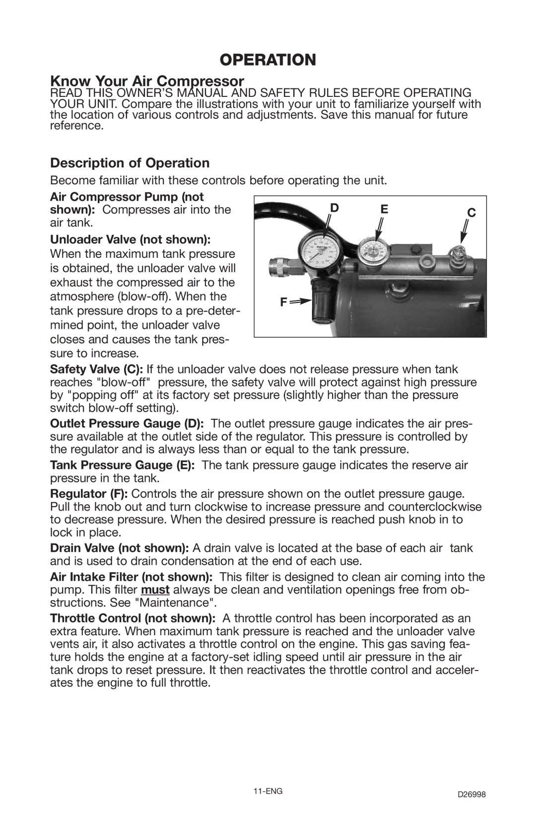
D EC
F![]()
Safety Valve (C): If the unloader valve does not release pressure when tank reaches
Outlet Pressure Gauge (D): The outlet pressure gauge indicates the air pres- sure available at the outlet side of the regulator. This pressure is controlled by the regulator and is always less than or equal to the tank pressure.
Tank Pressure Gauge (E): The tank pressure gauge indicates the reserve air pressure in the tank.
Regulator (F): Controls the air pressure shown on the outlet pressure gauge. Pull the knob out and turn clockwise to increase pressure and counterclockwise to decrease pressure. When the desired pressure is reached push knob in to lock in place.
Drain Valve (not shown): A drain valve is located at the base of each air tank and is used to drain condensation at the end of each use.
Air Intake Filter (not shown): This filter is designed to clean air coming into the pump. This filter must always be clean and ventilation openings free from ob- structions. See "Maintenance".
Throttle Control (not shown): A throttle control has been incorporated as an extra feature. When maximum tank pressure is reached and the unloader valve vents air, it also activates a throttle control on the engine. This gas saving fea- ture holds the engine at a
D26998 |