V. APPLICATION
A. KEYBOARD CONSTRUCTION
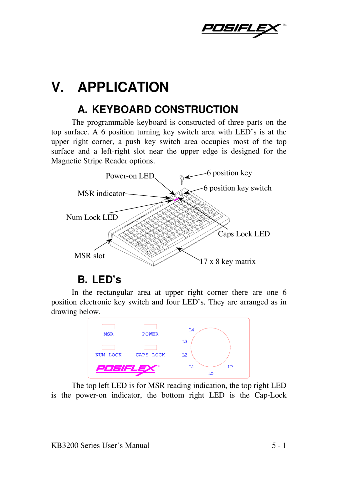
The programmable keyboard is constructed of three parts on the top surface. A 6 position turning key switch area with LED’s is at the upper right corner, a push key switch area occupies most of the top surface and a
6 position key | |
| |
MSR indicator | 6 position key switch |
|
Num Lock LED
MSR slot
~ ‘
!
| # 3 |
@ 2 |
|
1 | W |
Q |
|
Tab | A |
s |
|
Cap | K |
LOC | |
$ 4
E
S
t Shif
l Ctr
|
| 0 |
|
| 9 |
| * 8 | O |
| & 7 | I |
^ | U | K |
6 | ||
% 5 | Y | J |
T | H |
|
|
| N |
R | G |
|
|
| B |
F |
|
|
| V |
|
D |
|
|
| C |
|
X |
|
|
Z |
|
|
Alt |
|
|
| 8 |
| e |
| 7 Hom |
| 4 |
+ |
|
= |
|
_ |
|
- | r |
| Ente |
P | " |
| ’ |
: |
|
; | ? |
L | / |
| > . |
< |
|
, | t |
M | Al |
p |
|
9 PgU |
|
6 |
|
5 | n |
| 3 PgD |
2 | . |
| Del |
1 End | 00 |
0 | s |
t | In |
Shif |
|
l |
|
Ctr |
|
Caps Lock LED
17 x 8 key matrix
B. LED’s
In the rectangular area at upper right corner there are one 6 position electronic key switch and four LED’s. They are arranged as in drawing below.
MSR | POWER | L4 |
|
|
| ||
|
| L3 |
|
NUM LOCK | CAPS LOCK | L2 |
|
| TM | L1 | LP |
LO
The top left LED is for MSR reading indication, the top right LED is the
KB3200 Series User’s Manual | 5 - 1 |