a lock. The available positions for each key type are listed in the table below.
O = access |
| X = no access |
|
| |
|
| PRG | REG | Z | GT |
|
|
|
|
|
|
LP |
| O | X | X | X |
L0 |
| O | O | O | O |
L1 |
| O | O | O | O |
L2 |
| O | O | O | O |
L3 |
| O | X | O | O |
L4 |
| X | X | X | O |
|
|
|
|
|
|
The position L0 is designed to provide a “Security
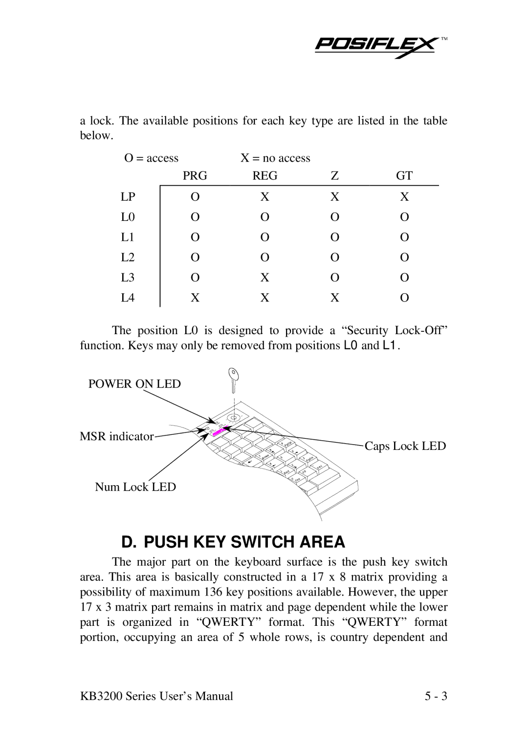
POWER ON LED
MSR indicator |
| 9 | p |
|
|
|
|
|
| PgU |
|
|
|
|
| 8 | 6 |
|
|
|
7 | e |
|
|
|
|
|
| Hom | 5 |
| 3 | n |
|
|
|
|
|
| PgD |
|
|
| 4 | 2 |
| . |
|
|
|
|
| l | ||
|
|
|
|
|
| De |
|
| 1 | d | 0 |
| |
|
|
| En | 0 |
|
|
Num Lock LED |
|
| 0 | s |
|
|
|
|
| In |
|
| |
|
|
|
|
|
| |
Caps Lock LED
D. PUSH KEY SWITCH AREA
The major part on the keyboard surface is the push key switch area. This area is basically constructed in a 17 x 8 matrix providing a possibility of maximum 136 key positions available. However, the upper 17 x 3 matrix part remains in matrix and page dependent while the lower part is organized in “QWERTY” format. This “QWERTY” format portion, occupying an area of 5 whole rows, is country dependent and
KB3200 Series User’s Manual | 5 - 3 |
