
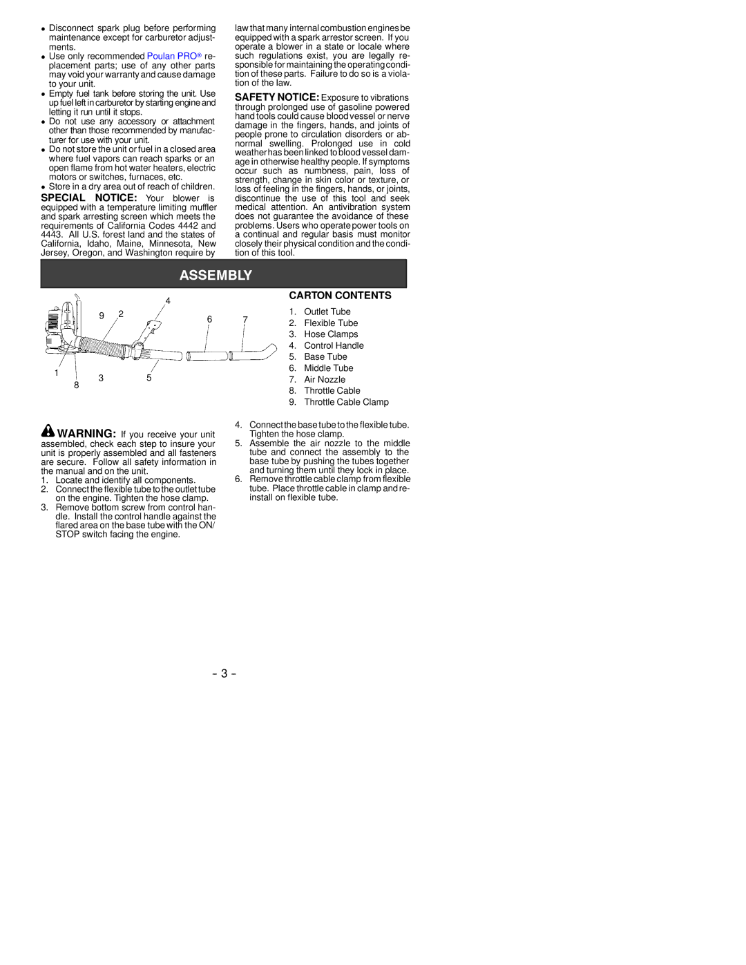
530088412 specifications
The Poulan 530088412 is a highly regarded replacement part designed for Poulan and Poulan Pro chainsaws. Known for its durability, efficiency, and ease of use, this part is essential for those seeking optimal performance from their equipment. The Poulan brand has built a reputation for producing reliable outdoor power equipment, and the 530088412 continues this legacy by offering users a product that meets stringent quality standards.One of the main features of the Poulan 530088412 is its superior construction. Made from high-quality materials, it is designed to withstand the rigors of heavy-duty use. This durability ensures that users can rely on the part for an extended period, reducing the need for frequent replacements. The design is specifically tailored to fit various models of Poulan chainsaws, making it a versatile option for those who own multiple models.
In terms of technology, the Poulan 530088412 incorporates advanced engineering to enhance its performance. It features a precise manufacturing process that ensures the part fits seamlessly into the chainsaw, enabling optimal operation. This precision helps maintain the chainsaw's performance, ensuring that it delivers consistent power and efficiency during cutting tasks.
Another characteristic that sets the Poulan 530088412 apart is its ease of installation. Users can quickly replace the part without requiring extensive technical knowledge or special tools. This user-friendly aspect makes it ideal for both seasoned professionals and those who may not have extensive experience in chainsaw maintenance.
Additionally, the Poulan 530088412 contributes to the overall safety of the chainsaw. By ensuring that the saw operates at peak performance, users can reduce the risk of accidents that stem from faulty or worn-out parts. Regular replacement of parts like the 530088412 can help maintain the chainsaw in optimal working condition, further enhancing user safety.
In summary, the Poulan 530088412 is a top choice for chainsaw users seeking a reliable, durable, and efficient replacement part. Its quality construction, advanced technology, and easy installation make it an essential component of chainsaw maintenance. Whether for professional landscapers or occasional users, investing in the Poulan 530088412 can lead to better performance and longevity of your chainsaw.