PP25E, 545186849 specifications
The Poulan 545186849, also known as the PP25E, is a versatile and robust outdoor power tool designed for residential use. It combines user-friendliness with advanced technology, making it an excellent option for homeowners who need reliable performance for lawn care and maintenance tasks. This model is particularly notable for its ergonomic design and lightweight construction, enhancing user comfort and reducing fatigue during extended periods of operation.One of the main features of the PP25E is its 25cc, 2-cycle engine. This power unit provides adequate power for various tasks, including trimming, edging, and cutting through tough grass and weeds. The engine has been engineered for smooth operation and easy starting, thanks to its reliable starter system. This ensures that users can quickly get to work without the frustration of dealing with difficult starts often associated with some outdoor power equipment.
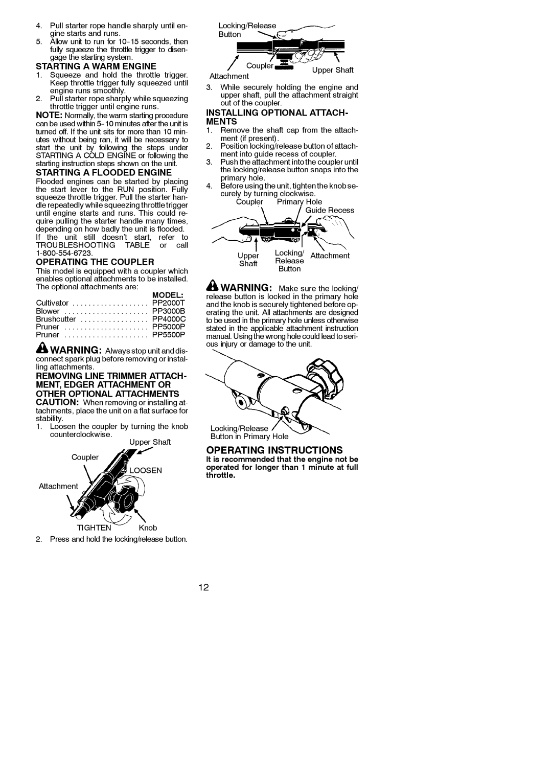
Another key characteristic of the Poulan PP25E is its versatility. The machine boasts a detachable powerhead that can be coupled with various attachments, such as lawn edgers, cultivators, and pruners. This adaptability allows homeowners to customize their equipment for different tasks, further enhancing its value and functionality. The ease of swapping out attachments makes it an excellent choice for those looking to streamline their outdoor maintenance routine.
User comfort is paramount in the design of the PP25E. The trimmer features an adjustable handle that allows users to tailor the operation to their height, ensuring optimal control and comfort. Additionally, the anti-vibration system incorporated into the design minimizes hand and arm fatigue, allowing for longer usage without discomfort.
The Poulan PP25E also incorporates advanced technologies to enhance its performance. The engine is designed to be highly fuel-efficient, which not only extends run time but also reduces emissions, aligning with environmental standards. The easy-access air filter simplifies maintenance, ensuring that users can keep their equipment in peak condition with minimal effort.
In summary, the Poulan 545186849 PP25E is a highly functional outdoor power tool equipped with a powerful yet efficient engine, versatile attachments, and user-friendly features. Its thoughtful design prioritizes comfort and ease of use, making it an excellent choice for homeowners seeking a reliable solution for their lawn care needs.

