SPECIAL NOTICE: This unit is equipped with a temperature limiting muffler and spark arresting screen which meets the require- ments of California Codes 4442 and 4443. All U.S. forest land and the states of California, Idaho, Maine, Minnesota, New Jersey, Ore- gon, and Washington require by law that many internal combustion engines be equipped with a spark arresting screen. If you
operate in a locale where such regulations ex- ist, you are legally responsible for maintaining the operating condition of these parts. Failure to do so is a violation of the law. For normal homeowner use, the muffler and spark arrest- ing screen will not require any service. After 50 hours of use, we recommend that your muffler be serviced or replaced by your autho- rized service dealer.
ASSEMBLY
CARTON CONTENTS
Check carton contents against the following list:
SPowerhead
SAttachment (with trimmer head installed) S Cupped washer
S Large nut for installing blades S Hex wrench
S Handlebar
S Bracket cover
S Bracket cover screws (2) S Metal blade shield
S Blade shield screws (4) S
S Plastic shield
S Wing nut (screwed onto plastic shield) S Shoulder strap with warning
S Container of oil
![]() WARNING: Always stop unit and dis- connect spark plug before performing any as- sembly procedures.
WARNING: Always stop unit and dis- connect spark plug before performing any as- sembly procedures.
![]() WARNING: If received assembled, repeat all steps to ensure your unit is properly assembled and all fasteners are secure.
WARNING: If received assembled, repeat all steps to ensure your unit is properly assembled and all fasteners are secure.
Examine parts for damage. Do not use dam- aged parts.
NOTE: If you need assistance or find parts missing or damaged, call
Finding fuel or oil residue on muffler is normal due to carburetor adjustments and testing done by the manufacturer.
TOOLS REQUIRED
SHex wrench (provided) S Adjustable wrench
S Phillips screwdriver
INSTALLING BRUSHCUTTER ATTACHMENT
CAUTION: When installing brushcutter at- tachment, place the unit on a flat surface for stability.
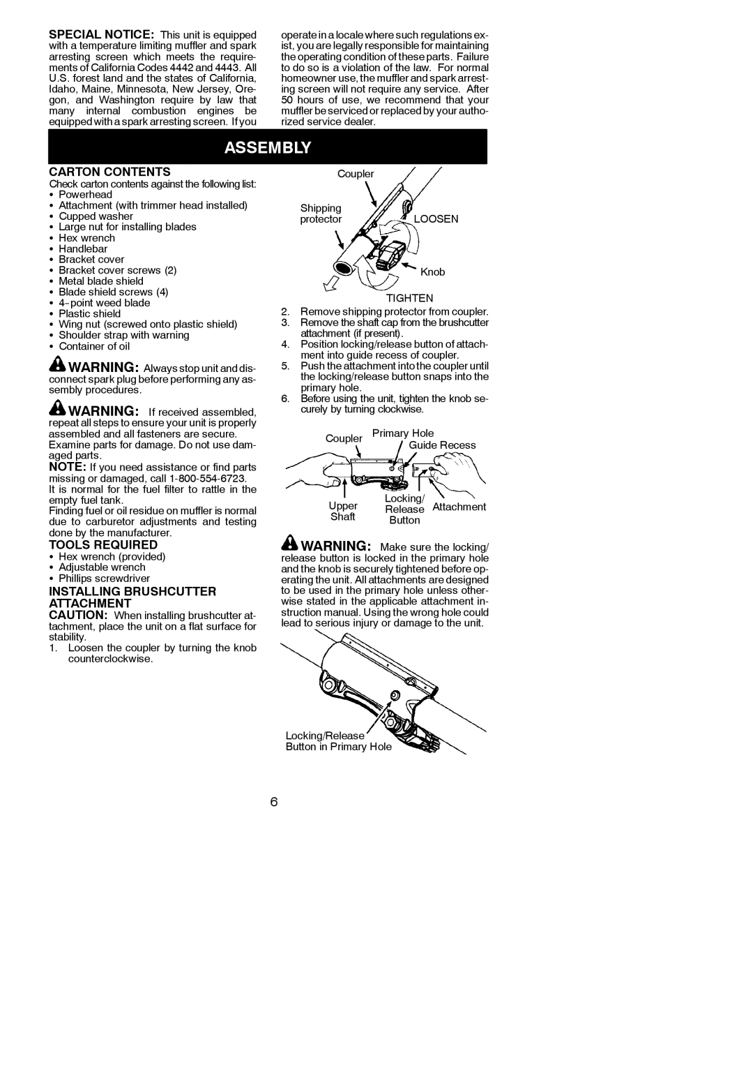
1.Loosen the coupler by turning the knob counterclockwise.
Coupler
Shipping
protectorLOOSEN
Knob
TIGHTEN
2.Remove shipping protector from coupler.
3.Remove the shaft cap from the brushcutter attachment (if present).
4.Position locking/release button of attach- ment into guide recess of coupler.
5.Push the attachment into the coupler until the locking/release button snaps into the primary hole.
6.Before using the unit, tighten the knob se- curely by turning clockwise.
Coupler Primary Hole
Guide Recess
Locking/
Upper Release Attachment
Shaft Button
![]() WARNING: Make sure the locking/ release button is locked in the primary hole and the knob is securely tightened before op- erating the unit. All attachments are designed to be used in the primary hole unless other- wise stated in the applicable attachment in- struction manual. Using the wrong hole could lead to serious injury or damage to the unit.
WARNING: Make sure the locking/ release button is locked in the primary hole and the knob is securely tightened before op- erating the unit. All attachments are designed to be used in the primary hole unless other- wise stated in the applicable attachment in- struction manual. Using the wrong hole could lead to serious injury or damage to the unit.
Locking/Release Button in Primary Hole
6