For assembly of optional attachments (see list on page 11), refer to the ASSEMBLY sec- tion of the applicable attachment instruction manual.
ATTACHING THE HANDLEBAR
![]() DANGER: To avoid serious injury, the barrier portion of the handlebar must be installed as shown to provide a barrier between operator and the spinning blade.
DANGER: To avoid serious injury, the barrier portion of the handlebar must be installed as shown to provide a barrier between operator and the spinning blade.
1. | Locate the decal on the handlebar. This |
| decal includes an arrow. Position the |
| handlebar with the mounting bracket at |
| the end of the arrow. |
2. | Position the bracket cover over the han- |
| dlebar. Again make sure the handlebar is |
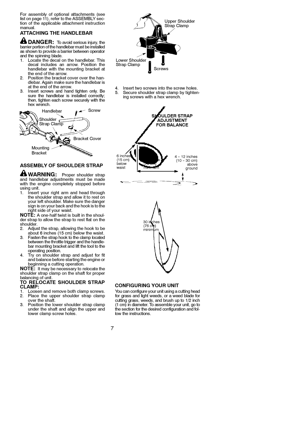
Lower Shoulder Strap Clamp
Upper Shoulder
Strap Clamp
Screws
at the end of the arrow. |
3. Insert screws and hand tighten only. Be |
sure the handlebar is installed correctly; |
then, tighten each screw securely with the |
hex wrench. |
Handlebar ![]() Screw
Screw
Shoulder
Strap Clamp
Bracket Cover
Mounting ![]()
Bracket
ASSEMBLY OF SHOULDER STRAP
![]() WARNING: Proper shoulder strap and handlebar adjustments must be made with the engine completely stopped before using unit.
WARNING: Proper shoulder strap and handlebar adjustments must be made with the engine completely stopped before using unit.
1.Insert your right arm and head through the shoulder strap and allow it to rest on your left shoulder. Make sure the danger sign is on your back and the hook is to the right side of your waist.
NOTE: A
2.Adjust the strap, allowing the hook to be about 6 inches (15 cm) below the waist.
3.Fasten the strap hook to the clamp located between the throttle trigger and the handle- bar mounting bracket and lift the tool to the operating position.
4.Try on shoulder strap and adjust for fit and balance before starting the engine or beginning a cutting operation.
NOTE: It may be necessary to relocate the shoulder strap clamp on the shaft for proper balancing of unit.
TO RELOCATE SHOULDER STRAP CLAMP:
1.Loosen and remove both clamp screws.
2.Place the upper shoulder strap clamp over the shaft.
3.Position the lower shoulder strap clamp under the shaft and align the upper and lower clamp screw holes.
4.Insert two screws into the screw holes.
5.Secure shoulder strap clamp by tighten- ing screws with a hex wrench.
SHOULDER STRAP
ADJUSTMENT
FOR BALANCE
6 inches |
|
| 4 |
(15 cm) |
| 30 inches | (10 |
below |
| (76 cm) | above |
waist |
| minimum | ground |
|
|
|
|
30inches
(76 cm) minimum
CONFIGURING YOUR UNIT
You can configure your unit using a cutting head for grass and light weeds, or a weed blade for cutting grass, weeds, and brush up to 1/2 inch (1 cm) in diameter. To assemble your unit, go to the section for the desired configuration and fol- low the instructions.
7