CARTON CONTENTS
Check carton contents for the following:
Sbrushcutter
Shandlebar screws (2)
S blade shield screws (4) S cupped washer
S large nut for installing blade S long hex wrench
S short hex wrench S bracket cover
S metal shield S plastic shield
S shoulder strap with warning S weed blade
S trimmer head S handlebar
S container of oil
Examineparts for damage. Donot usedam- aged parts.
NOTE: If you need assistance or find parts missing or damaged, call
Itis normalfor thefuelfiltertorattleintheempty fuel tank.
Findingfuelor oilresidue onmuffler is normal
duetocarburetoradjustmentsandtestingdone by the manufacturer.
ASSEMBLY
WARNING:Ifreceivedassembled,repeat all steps to ensure your unit is properly as- sembled and all fasteners are secure.
TOOLS REQUIRED
S2 hex wrenches (provided) S adjustable wrench
S phillips screwdriver.
ATTACHING THE HANDLEBAR
DANGER:Thebarrierportionofthehandlebar mustbeinstalledasshowntoprovideabarrier
between operator and the spinning blade.
SLocatethedecalonthehandlebar.Thisde- cal includes two arrows. Position thehan-
dlebar with themounting bracketbetween these arrows.
SPositionthebracketcoverover thehandle-
bar. Again make sure the handlebar is be- tween the arrows.
SInsert screws and hand tighten only. Be sure the handlebar is installed correctly; then,tighteneach screwsecurely withthe short hex wrench.
HandlebarScrew
BracketCover
Mounting
Bracket
ASSEMBLY OF SHOULDER STRAP
WARNING:Propershoulderstrapandhan- dlebaradjustmentsbeforestartingtheengine are required.
STry onshoulder strapand adjustfor fitand balancebeforestartingtheengineorbegin-
ning a cutting operation.
SInsertyour rightarm andhead throughthe shoulder strap and allow it to rest on your
leftshoulder. Makesure thedanger signis on your back and the hook is to the right side of your waist.
SAdjust the strap, allowing the hook to be
about 6 inches below the waist.
SFastenthestraphook tothe clamplocated betweenthetrigger handleand themount-
ing block and lift the tool to the operating position.
CONFIGURING YOUR UNIT
You can configure your unit using a cutting
head for grass and light weeds, or a weed bladefor cuttinggrass, weeds,and brushup
to1/2inchindiameter.Toassembleyourunit,
gotothesectionfor thedesiredconfiguration and follow the instructions.
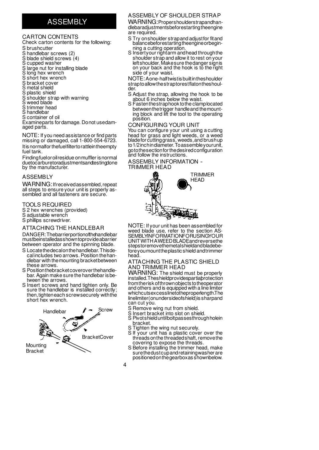
ASSEMBLY INFORMATION - TRIMMER HEAD
TRIMMER
HEAD
NOTE: If your unit has been assembled for weed blade use, refer to the section AS-
SEMBLYINFORMATIONFORUSINGYOUR
UNIT WITHAWEEDBLADEandreversethe stepstoremovethemetalshieldandbladebe-
foreyoumounttheplastic shield andtrimmer head.
ATTACHING THE PLASTIC SHIELD AND TRIMMER HEAD
WARNING: The shield must be properly installed.Theshieldprovidespartialprotection
fromtherisk ofthrownobjects totheoperator and others and is equipped with a line limiter
whichcutsexcesslinetotheproperlength.The
linelimiter(onundersideofshield)is sharpand can cut you.
SRemove wing nut from shield.
SInsert bracket into slot on shield.
SPivotshielduntilboltpassesthroughholein
bracket.
STighten the wing nut securely.
SIf your unit has a plastic cover over the
threads onthe threadedshaft, removethe covering to expose the threads.
SBefore installing the trimmer head, make
surethedustcupandretainingwasher are positionedonthegearboxas shownbelow.
4