4224B specifications
The Powermatic 4224B is a premier wood lathe that exemplifies robust engineering and advanced technology, making it a favored choice among both professionals and hobbyists in the woodworking community. This lathe is designed to handle large workpieces with precision and ease, ensuring superior performance during various turning tasks.One of the standout features of the Powermatic 4224B is its powerful 2-horsepower motor, which provides ample torque even at low speeds. This motor is housed in a heavy-duty cast iron construction, ensuring stability and reducing vibrations while in operation. The lathe's bed is also made from solid cast iron, offering a sturdy foundation and longevity that can withstand rigorous use.
The 4224B boasts an impressive 24-inch swing over the bed, allowing woodworkers to tackle large bowls and hollow forms. With an overall length of 42 inches, it accommodates a wide range of projects, making it versatile for different turning applications. It features a user-friendly digital readout for spindle speed, allowing operators to quickly and efficiently adjust settings to suit their specific needs.
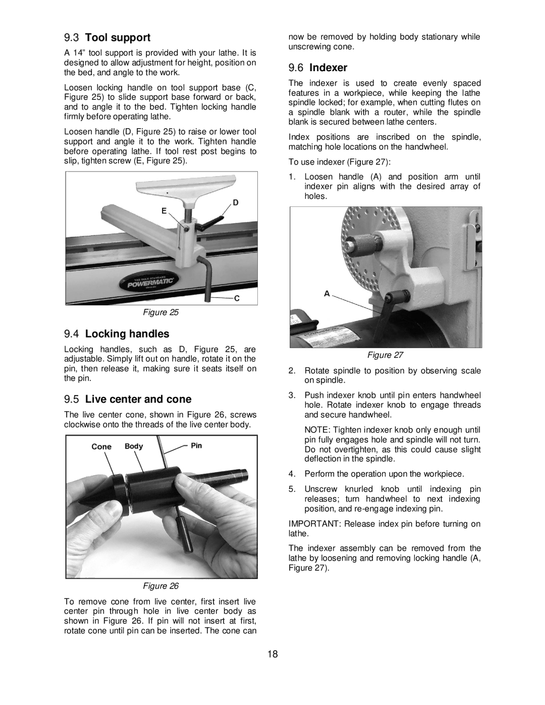
In terms of technology, the Powermatic 4224B integrates an innovative SteadyRest and a Tailstock that provides enhanced stability and control during the turning process. The lathe also incorporates a 24-position index head, enabling precise indexing for decorative turning and ensuring accuracy in each rotation.
Another significant characteristic is its variable speed control, allowing users to switch speeds from 40 to 3200 RPM, catering to different materials and project requirements. The quick-change drive system enhances the ease of switching between speeds without the need for additional tools.
The electronic braking system adds an essential safety feature, rapidly stopping the spindle when needed, enhancing user confidence during operation. Additionally, the lathe comes equipped with adjustable feet, ensuring it can be leveled on uneven surfaces.
Overall, the Powermatic 4224B wood lathe is a well-rounded tool that combines power, precision, and versatility, making it an ideal choice for serious woodturners looking to elevate their craft. Its durable design, advanced features, and user-friendly operation make it an investment that can significantly enhance any woodworking workshop.

