Assembly of Accessory Workbench
If further clarification is needed for any assembly procedure, consult the breakdown on page 7.
Tools Required for Assembly :
(not included)
6mm hex (Allen) wrench
Cross point (Phillips) screwdriver 13mm
If desired, apply stain or finish over the natural wood parts before assembly.
TIP: Steps 1 through 4 below are easier if done with table assembly upside down and flat on the floor.
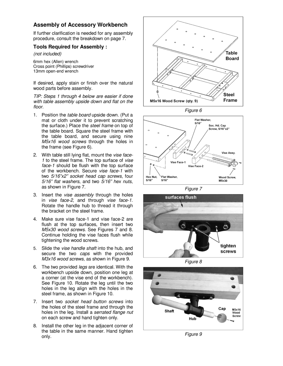
1.Position the table board upside down. (Put a mat or cloth under it to prevent scratching the surface.) Place the steel frame on top of the table board. Square the steel frame with the table board, and secure using nine M5x16 wood screws through the holes in the frame (see Figure 6).
2.With table still lying flat, mount the vise face- 1 to the steel frame. The top surface of vise
3.Insert the vise assembly through the holes in vise
4.Make sure vise
5.Slide the vise handle shaft into the hub, and secure the two caps with the provided M3x16 wood screws, as shown in Figure 9.
6.The two provided legs are identical. With the workbench upside down, position one leg at a corner (at the vise end of the workbench). See Figure 10. Rotate the leg until the two holes in the leg align with the holes in the steel frame, as shown in Figure 10.
7.Insert two socket head button screws into the holes of the steel frame and through the holes in the leg. Install a serrated flange nut on each screw and hand tighten only.
8.Install the other leg in the adjacent corner of the table in the same manner. Hand tighten only.
Figure 6
Figure 7
Figure 8
Figure 9