Manuals
/
Precision Power
/
Home Audio
/
Stereo Amplifier
Precision Power
D500/1, D2000/1, D3000/1, D1000/1
manual
Powerlocktm
Models:
D1000/1
D500/1
D3000/1
D2000/1
1
10
23
23
Download
23 pages
31.61 Kb
7
8
9
10
11
12
13
14
Troubleshooting
Specs
Front Plate Diagrams
QBASSTM Settings
Nominal Power Ratings
Service
Page 10
Image 10
Page 9
Page 11
Page 10
Image 10
Page 9
Page 11
Contents
D1000/1
AMPLIFIER MODELS
D500/1
D2000/1
TABLE OF CONTENTS
SERVICE
CONGRATULATIONS
CEA SPECIFICATIONS
FEATURES
WHAT’S INCLUDED
General Specifications
SPECIFICATIONS
Nominal Power Ratings
D500/1
Fuse
The LEDs provide the following indications
Small flat blade screwdriver
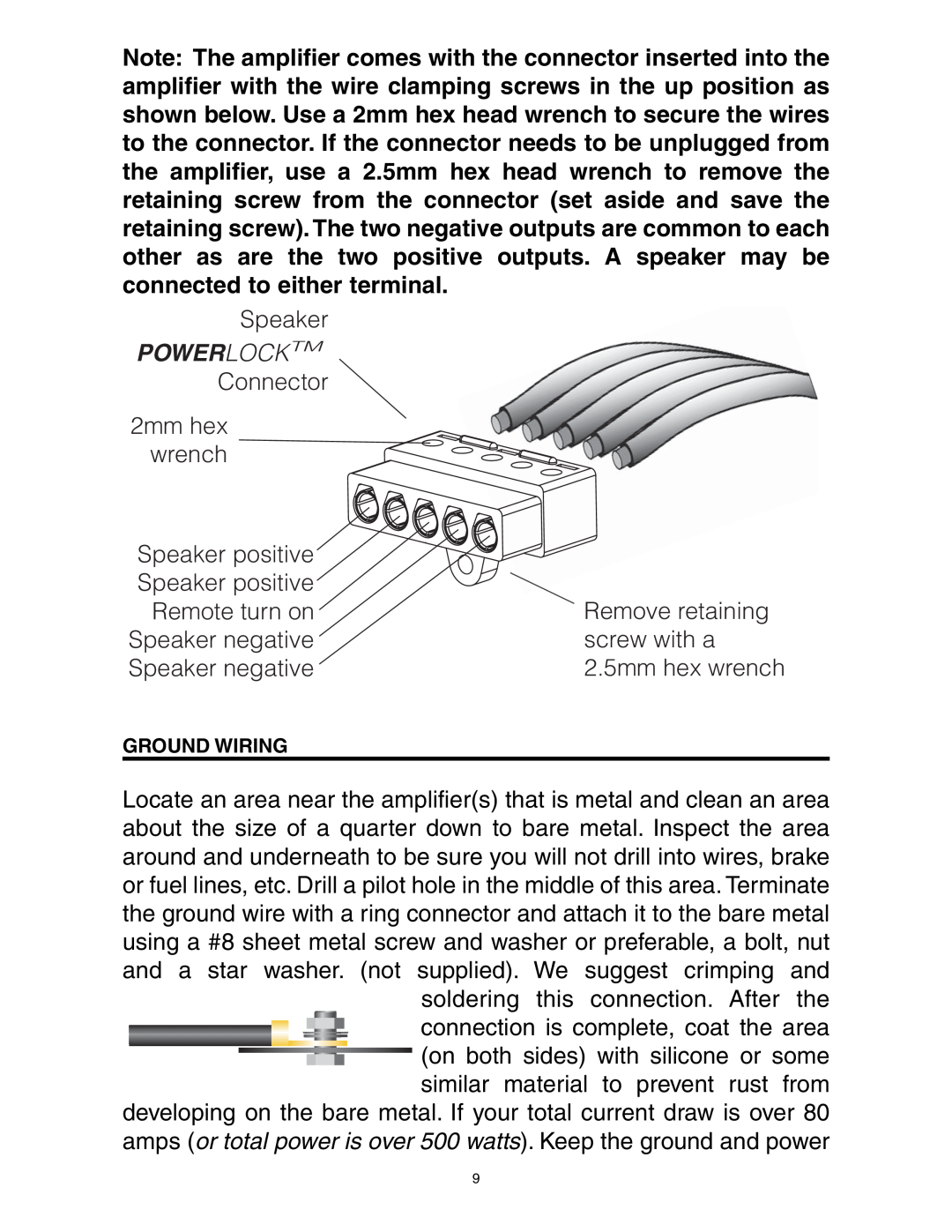
When using 16 gauge wire or larger, run the speaker wires from the amplifier location through the vehicle to the speakers. Observe the same precautions for routing these wires that you followed for running the power and remote turn on wires. Cut off excess and, using wire strippers, strip 1/4-inchof insulation. Locate the speaker/remote turn- on PowerLockTM connector. Using a hex wrench loosen the screws on the upperside of the connector. Insert the speaker leads into the end and secure with the hex wrench. Check to be sure youve maintained proper polarity before securing each wire
POWERLOCKTM
Total RMS output X 1.3 = Total Input Wattage
1300W= 108 Amps total current draw 12V
3mm hex
Power wires
POWERLOCK CONNECTORS
wrench
FRONT PLATE DIAGRAMS
XOVER
12 D500/1, D1000/1
END PLATE DIAGRAMS
D2000/1, D3000/1
ADVANCED INSTRUMENTATION INPUT
INPUTS
SOURCE Headunit
Optional QBASS REMOTETM
QBASS PLUSTM
QBASS PLUS SPECIFICATIONS
QBASSTM Settings
D500/1, D1000/1, D2000/1, and D3000/1
TC-XCROSSOVER
CROSSOVER DETENT CHART
HIGH MASS INTERNAL HEATSINK
ADJUSTING INPUT GAIN
TROUBLESHOOTING
AP-IVPROTECTION CIRCUIT
SAME CHANNEL
Precision PowerTM Dealer or
OPPOSITE CHANNEL
OPPOSITE CHANNEL
LIMITED TWO YEAR CONSUMER WARRANTY
Top
Page
Image
Contents