PAR224 specifications
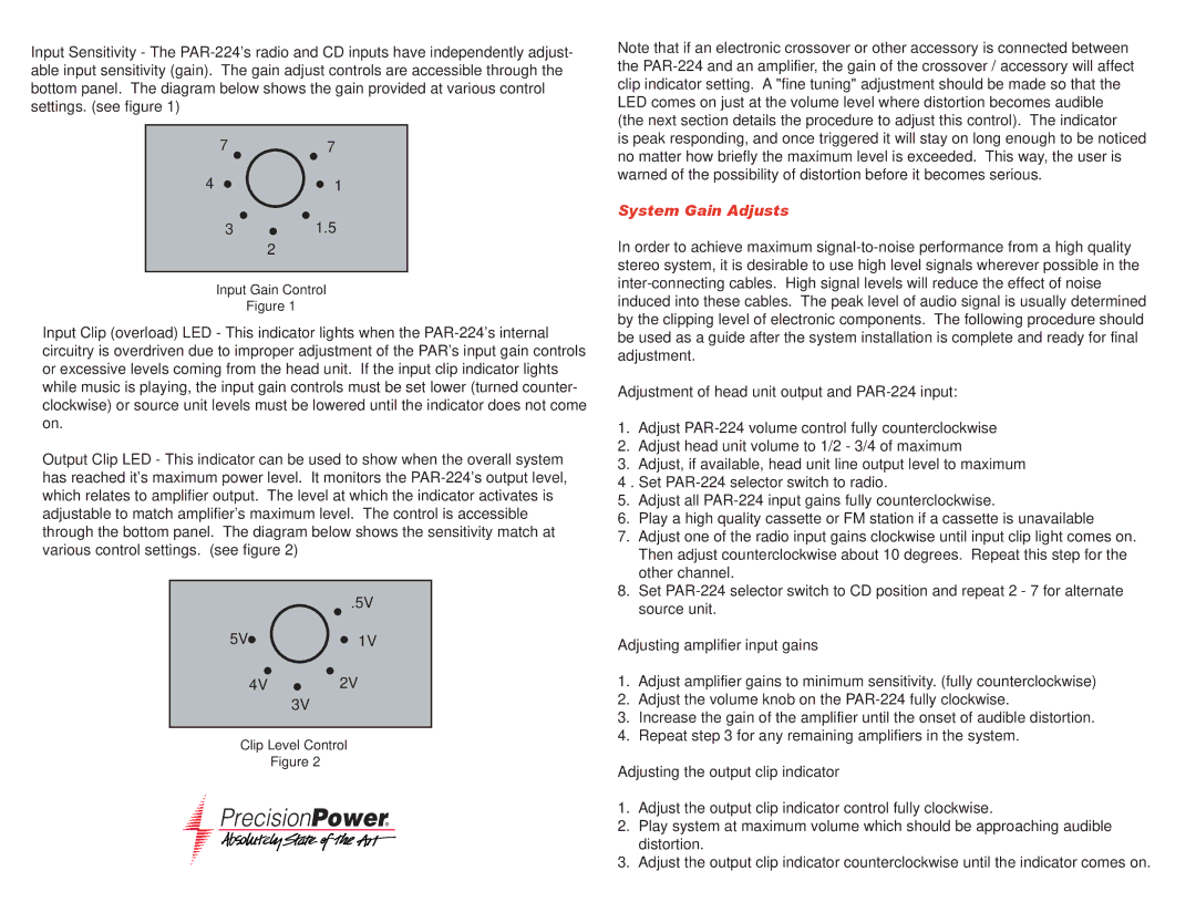
The Precision Power PAR224 is a remarkable amplifier that stands out in the automotive audio industry due to its advanced features, technologies, and robust performance. Designed specifically for car audio enthusiasts who demand high-quality sound, this amplifier delivers a powerful and clear audio experience that enhances any vehicle's sound system.One of the standout features of the PAR224 is its impressive power output. With a maximum power rating of 1200 watts, this amplifier offers sufficient power to drive subwoofers and speakers seamlessly. It features a two-channel configuration, which allows for versatile installation options, including bridging capabilities to power larger systems. The ability to connect multiple speakers without distortion ensures that users can enjoy rich, immersive sound.
Moreover, the PAR224 is equipped with advanced circuit protection technologies. These technologies prevent overheating and short circuits, significantly extending the lifespan of the amplifier. The built-in protection circuits monitor the temperature and automatically adjust the performance to prevent damage, creating a reliable option for those who prioritize durability and safety in their audio systems.
The amplifier also boasts high-quality components, including precision capacitors and heavy-duty terminals. These components contribute to efficient power transfer and excellent sound quality, ensuring minimal signal loss. Additionally, the amplifier features adjustable crossover settings, allowing users to fine-tune the sound according to their preferences. Whether opting for a low-pass filter for subwoofers or a high-pass filter for speakers, users can achieve optimal sound clarity and definition.
Another notable characteristic is the sleek design of the PAR224. Its compact size allows for easy installation in various vehicle types without compromising on performance. The stylish aluminum chassis not only enhances the aesthetic appeal but also aids in heat dissipation, further improving longevity.
In summary, the Precision Power PAR224 amplifier is a leading choice for car audio enthusiasts, offering an impressive combination of power, durability, and sound quality. Its advanced features, such as circuit protection, adjustable crossovers, and high-quality components, ensure that users receive exceptional audio performance. With its stylish design and reliable operation, the PAR224 is set to transform any car audio system into an immersive sound experience.

