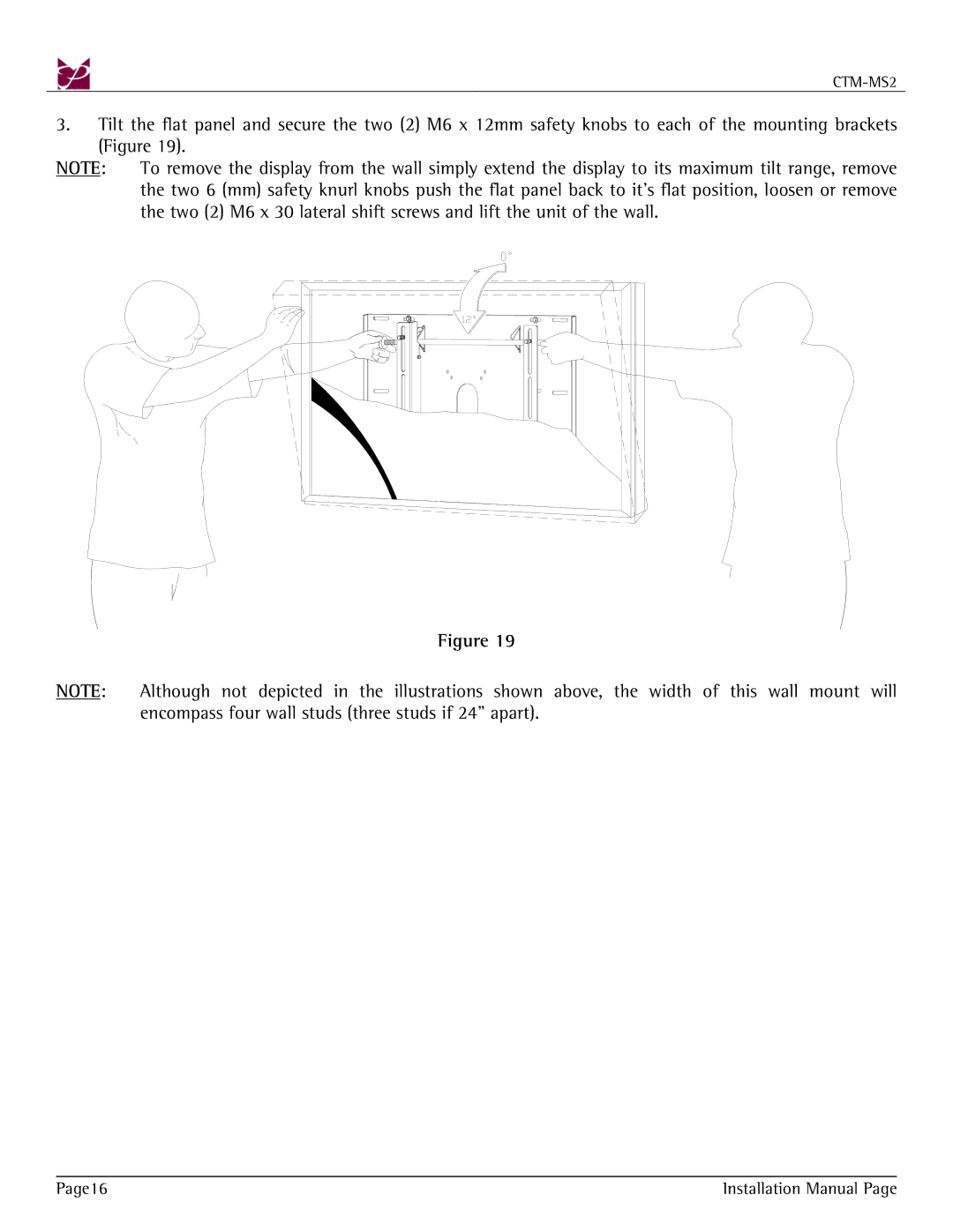
3.Tilt the flat panel and secure the two (2) M6 x 12mm safety knobs to each of the mounting brackets (Figure 19).
NOTE: To remove the display from the wall simply extend the display to its maximum tilt range, remove the two 6 (mm) safety knurl knobs push the flat panel back to it’s flat position, loosen or remove the two (2) M6 x 30 lateral shift screws and lift the unit of the wall.
Figure 19
NOTE: Although not depicted in the illustrations shown above, the width of this wall mount will encompass four wall studs (three studs if 24” apart).
Page16 | Installation Manual Page |
