I I I . Y O U R P O W E R C H A I R
Main Circuit Breaker: The main circuit breaker is a safety feature built into your power chair. When the batteries and the motors are heavily strained (e.g., from excessive loads), the main circuit breaker trips to prevent damage to the motors and the electronics. If the circuit trips, allow your power chair to “rest” for approximately one minute. Next, push in the circuit breaker button, turn on the controller, and continue normal operation. If the main circuit breaker continues to trip repeat- edly, contact your authorized Pride Provider.
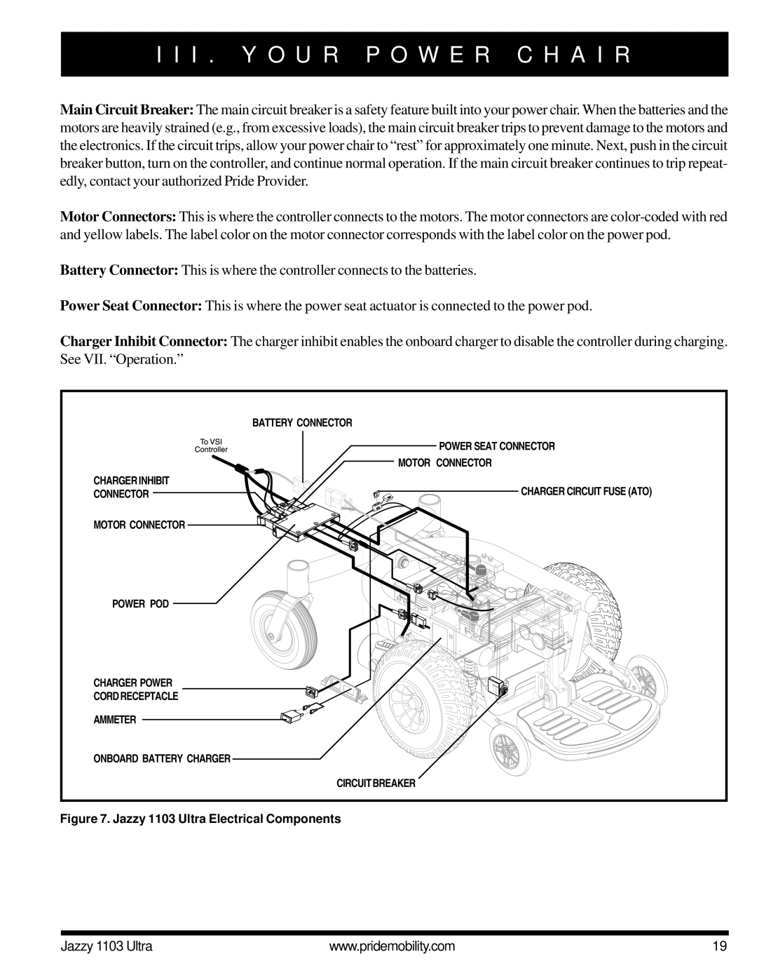
Motor Connectors: This is where the controller connects to the motors. The motor connectors are
Battery Connector: This is where the controller connects to the batteries.
Power Seat Connector: This is where the power seat actuator is connected to the power pod.
Charger Inhibit Connector: The charger inhibit enables the onboard charger to disable the controller during charging. See VII. “Operation.”
| BATTERY CONNECTOR |
| POWER SEAT CONNECTOR |
| MOTOR CONNECTOR |
CHARGER INHIBIT | CHARGER CIRCUIT FUSE (ATO) |
CONNECTOR | |
MOTOR CONNECTOR |
|
POWER POD |
|
CHARGER POWER |
|
CORD RECEPTACLE |
|
AMMETER |
|
ONBOARD BATTERY CHARGER |
|
| CIRCUIT BREAKER |
Figure 7. Jazzy 1103 Ultra Electrical Components
Jazzy 1103 Ultra | www.pridemobility.com | 19 |