I I I . Y O U R G O - C H A I R
CONTROLLER CONNECTOR | SEAT PEDESTAL |
BATTERY BOX
FREEWHEELLEVER
CIRCUIT BREAKER
REAR SECTION
FRONT SECTION
BATTERY BOX CHARGER PORT
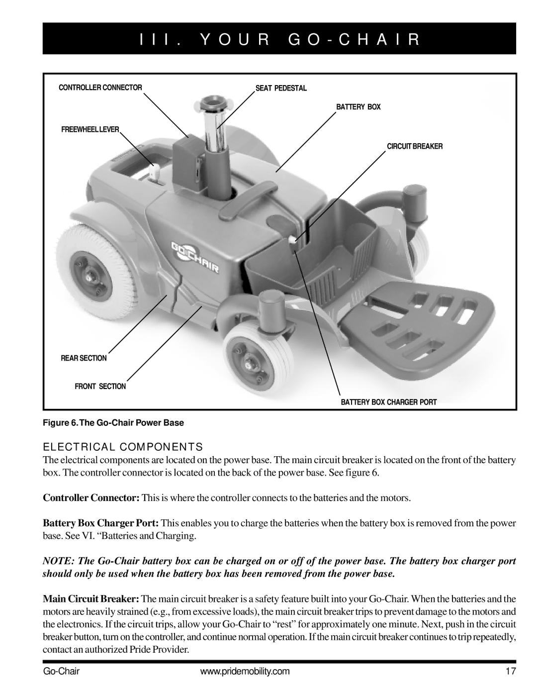
Figure 6.The Go-Chair Power Base
ELECTRICAL COMPONENTS
The electrical components are located on the power base. The main circuit breaker is located on the front of the battery box. The controller connector is located on the back of the power base. See figure 6.
Controller Connector: This is where the controller connects to the batteries and the motors.
Battery Box Charger Port: This enables you to charge the batteries when the battery box is removed from the power base. See VI. “Batteries and Charging.
NOTE: The
Main Circuit Breaker: The main circuit breaker is a safety feature built into your
www.pridemobility.com | 17 |