ASSEMBLY
•Assembly requires two persons.
•Place all parts in a cleared area and remove the packing materials. Do not dispose of the packing materials until you finish assembly.
•The underside of the walking belt is coated with
•To identify small parts, see page 6.
•Assembly requires the following tools:
the included hex keys one Phillips screwdriver scissors
•To avoid damaging parts, do not use power tools.
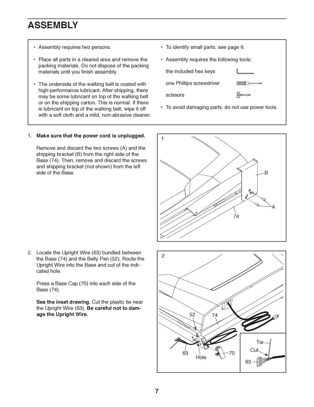
1. Make sure that the power cord is unplugged. | 1 | |
| ||
Remove and discard the two screws (A) and the |
| |
shipping bracket (B) from the right side of the |
| |
Base (74). Then, remove and discard the screws |
| |
and shipping bracket (not shown) from the left | B | |
side of the Base. | ||
| A | |
| 74 | |
2. Locate the Upright Wire (63) bundled between | 2 | |
the Base (74) and the Belly Pan (52). Route the | ||
| ||
Upright Wire into the Base and out of the indi- |
| |
cated hole. |
| |
Press a Base Cap (70) into each side of the |
| |
Base (74). |
|
See the inset drawing. Cut the plastic tie near |
|
|
the Upright Wire (63). Be careful not to dam- |
|
|
age the Upright Wire. | 52 | 74 |
|
|
| Tie |
63 | Hole | 70 | Cut |
| |||
|
| 63 | |
|
|
|
7
