ASSEMBLY
Make sure that the power cord is unplugged. Assembly requires two persons. Set the treadmill in a cleared area and remove all packing materials. Do not dispose of the packing materials until assembly is completed. Note: The underside of the treadmill walking belt is coated with
Assembly requires the included hex keys | and your own Phillips screwdriver | and | |
adjustable wrench | . |
|
|
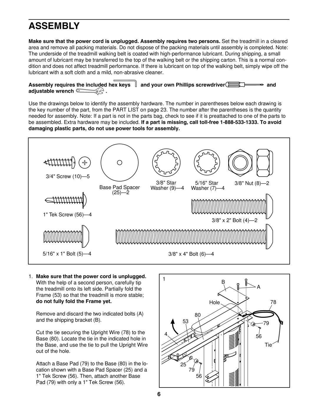
Use the drawings below to identify the assembly hardware. The number in parentheses below each drawing is the key number of the part, from the PART LIST on page 23. The number after the parentheses is the quantity needed for assembly. Note: If a part is not in the parts bag, check to see if it is preattached to one of the parts to be assembled. Extra hardware may be included. If a part is missing, call
3/4" Screw |
|
|
|
Base Pad Spacer | 3/8" Star | 5/16" Star | 3/8" Nut |
Washer | Washer |
| |
|
|
| |
1" Tek Screw |
| 3/8" x 2" Bolt | |
|
| ||
5/16" x 1" Bolt | 3/8" x 4" Bolt |
| |
1. Make sure that the power cord is unplugged. | 1 | B |
|
With the help of a second person, carefully tip |
| ||
| A | ||
the treadmill onto its left side. Partially fold the |
|
| |
|
|
| |
Frame (53) so that the treadmill is more stable; |
|
|
|
do not fully fold the Frame yet. |
| Hole | 78 |
Remove and discard the two indicated bolts (A) |
| 80 |
|
and the shipping bracket (B). | 53 |
| 79 |
|
|
| |
Cut the tie securing the Upright Wire (78) to the | 4 |
| 56 |
Base (80). Locate the tie in the indicated hole in |
| ||
|
| ||
|
|
| |
the Base, and use the tie to pull the Upright Wire |
|
| Tie |
out of the hole. |
|
|
|
Attach a Base Pad (79) to the Base (80) in the lo- | 25 |
|
|
cation shown with a Base Pad Spacer (25) and a |
| 79 |
|
1" Tek Screw (56). Then, attach another Base |
| 56 |
|
Pad (79) with only a 1" Tek Screw (56). |
|
|
|
| 6 |
|
|