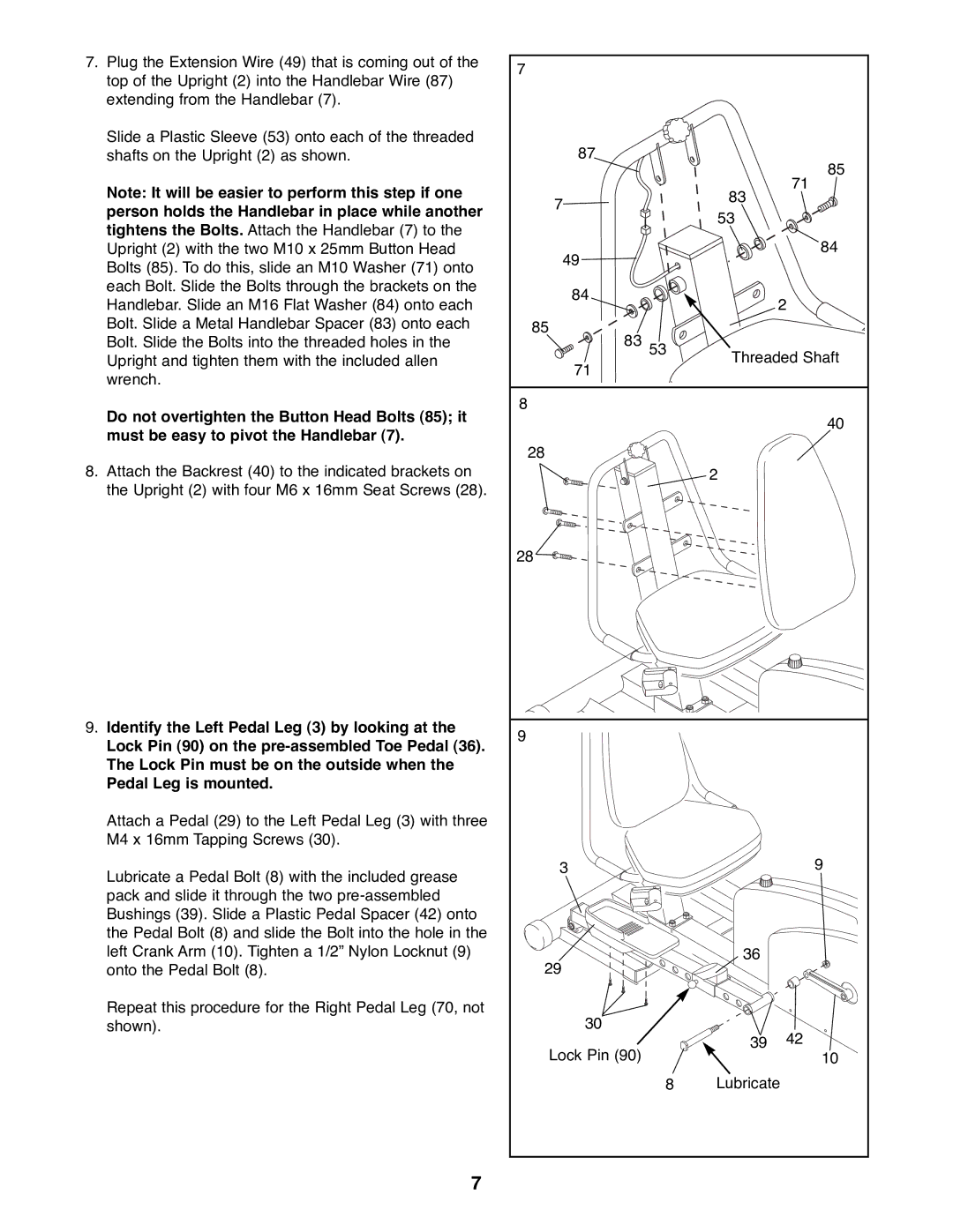
7.Plug the Extension Wire (49) that is coming out of the top of the Upright (2) into the Handlebar Wire (87) extending from the Handlebar (7).
Slide a Plastic Sleeve (53) onto each of the threaded shafts on the Upright (2) as shown.
Note: It will be easier to perform this step if one person holds the Handlebar in place while another tightens the Bolts. Attach the Handlebar (7) to the Upright (2) with the two M10 x 25mm Button Head Bolts (85). To do this, slide an M10 Washer (71) onto each Bolt. Slide the Bolts through the brackets on the Handlebar. Slide an M16 Flat Washer (84) onto each Bolt. Slide a Metal Handlebar Spacer (83) onto each Bolt. Slide the Bolts into the threaded holes in the Upright and tighten them with the included allen wrench.
Do not overtighten the Button Head Bolts (85); it must be easy to pivot the Handlebar (7).
8.Attach the Backrest (40) to the indicated brackets on the Upright (2) with four M6 x 16mm Seat Screws (28).
9.Identify the Left Pedal Leg (3) by looking at the Lock Pin (90) on the
Attach a Pedal (29) to the Left Pedal Leg (3) with three M4 x 16mm Tapping Screws (30).
Lubricate a Pedal Bolt (8) with the included grease pack and slide it through the two
Repeat this procedure for the Right Pedal Leg (70, not shown).
7
7 |
|
| |
87 |
| 85 | |
|
| ||
| 83 | 71 | |
7 |
| ||
53 |
| ||
|
| ||
49 |
| 84 | |
|
| ||
84 |
| 2 | |
|
| ||
85 |
|
| |
83 53 | Threaded Shaft | ||
71 | |||
|
| ||
8 |
|
| |
|
| 40 | |
28 |
|
| |
| 2 |
| |
28 |
|
| |
9 |
|
| |
3 |
| 9 | |
29 | 36 |
| |
|
| ||
30 |
| 42 | |
Lock Pin (90) | 39 | ||
| 10 | ||
8 | Lubricate | ||
