ASSEMBLY
Assembly requires two persons. Set the treadmill in a cleared area and remove all packing materials. Do not dispose of the packing materials until assembly is completed. Note: The underside of the treadmill walking belt is coated with
Assembly requires the included allen wrenches | and your own phillips screwdriver | , | |
wire cutters | , and needlenose pliers | . |
|
To identify small parts, use the PART IDENTIFICATION CHART attached in the center of this manual. Note: If a part is not in the parts bag, first check to see if it has been
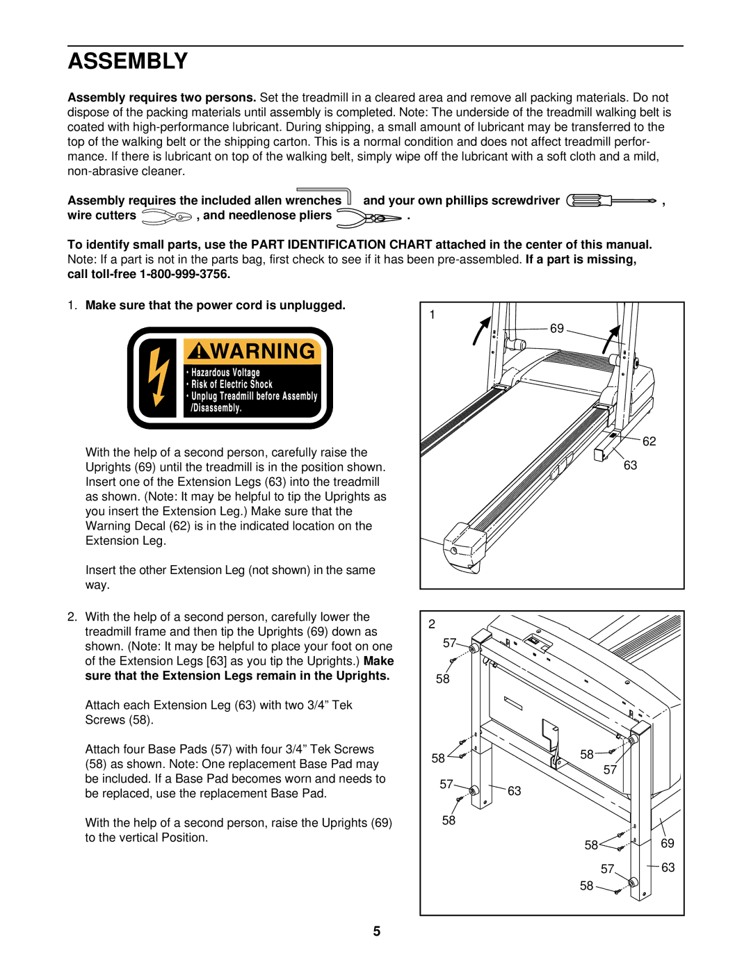
1.Make sure that the power cord is unplugged.
With the help of a second person, carefully raise the Uprights (69) until the treadmill is in the position shown. Insert one of the Extension Legs (63) into the treadmill as shown. (Note: It may be helpful to tip the Uprights as you insert the Extension Leg.) Make sure that the Warning Decal (62) is in the indicated location on the Extension Leg.
Insert the other Extension Leg (not shown) in the same way.
2.With the help of a second person, carefully lower the treadmill frame and then tip the Uprights (69) down as shown. (Note: It may be helpful to place your foot on one of the Extension Legs [63] as you tip the Uprights.) Make sure that the Extension Legs remain in the Uprights.
Attach each Extension Leg (63) with two 3/4” Tek Screws (58).
Attach four Base Pads (57) with four 3/4” Tek Screws
(58)as shown. Note: One replacement Base Pad may be included. If a Base Pad becomes worn and needs to be replaced, use the replacement Base Pad.
With the help of a second person, raise the Uprights (69) to the vertical Position.
1 | 69 |
|
|
| |
|
| 62 |
|
| 63 |
2 |
|
|
57 |
|
|
58 |
|
|
58 | 58 |
|
57 |
| |
|
| |
57 | 63 |
|
|
| |
58 |
|
|
| 58 | 69 |
| 57 | 63 |
| 58 |
|
5