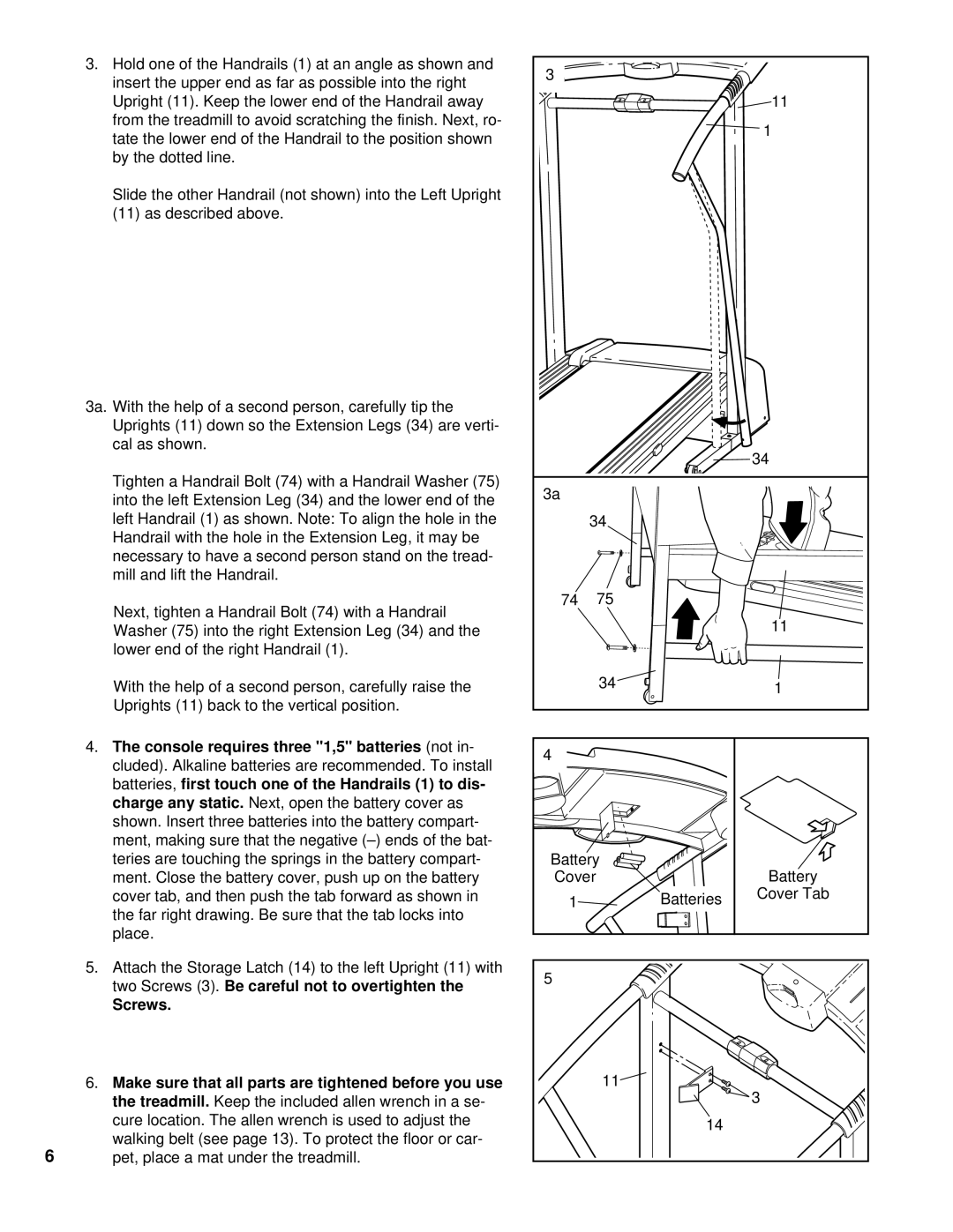
3.Hold one of the Handrails (1) at an angle as shown and insert the upper end as far as possible into the right Upright (11). Keep the lower end of the Handrail away from the treadmill to avoid scratching the finish. Next, ro- tate the lower end of the Handrail to the position shown by the dotted line.
Slide the other Handrail (not shown) into the Left Upright (11) as described above.
3a. With the help of a second person, carefully tip the Uprights (11) down so the Extension Legs (34) are verti- cal as shown.
Tighten a Handrail Bolt (74) with a Handrail Washer (75) into the left Extension Leg (34) and the lower end of the left Handrail (1) as shown. Note: To align the hole in the Handrail with the hole in the Extension Leg, it may be necessary to have a second person stand on the tread- mill and lift the Handrail.
Next, tighten a Handrail Bolt (74) with a Handrail Washer (75) into the right Extension Leg (34) and the lower end of the right Handrail (1).
With the help of a second person, carefully raise the Uprights (11) back to the vertical position.
4.The console requires three "1,5" batteries (not in- cluded). Alkaline batteries are recommended. To install batteries, first touch one of the Handrails (1) to dis- charge any static. Next, open the battery cover as shown. Insert three batteries into the battery compart- ment, making sure that the negative
5.Attach the Storage Latch (14) to the left Upright (11) with two Screws (3). Be careful not to overtighten the
Screws.
6.Make sure that all parts are tightened before you use the treadmill. Keep the included allen wrench in a se- cure location. The allen wrench is used to adjust the
walking belt (see page 13). To protect the floor or car-
6pet, place a mat under the treadmill.
3 |
|
|
|
|
|
| 11 |
|
|
| 1 |
|
|
| 34 |
3a |
|
|
|
34 |
|
| |
74 | 75 |
|
|
|
|
| 11 |
| 34 |
| 1 |
|
|
| |
4 |
|
|
|
Battery |
| Battery | |
Cover |
|
| |
1 |
| Batteries | Cover Tab |
|
| ||
5 |
|
|
|
| 11 |
| 3 |
|
|
| |
|
| 14 |
|
