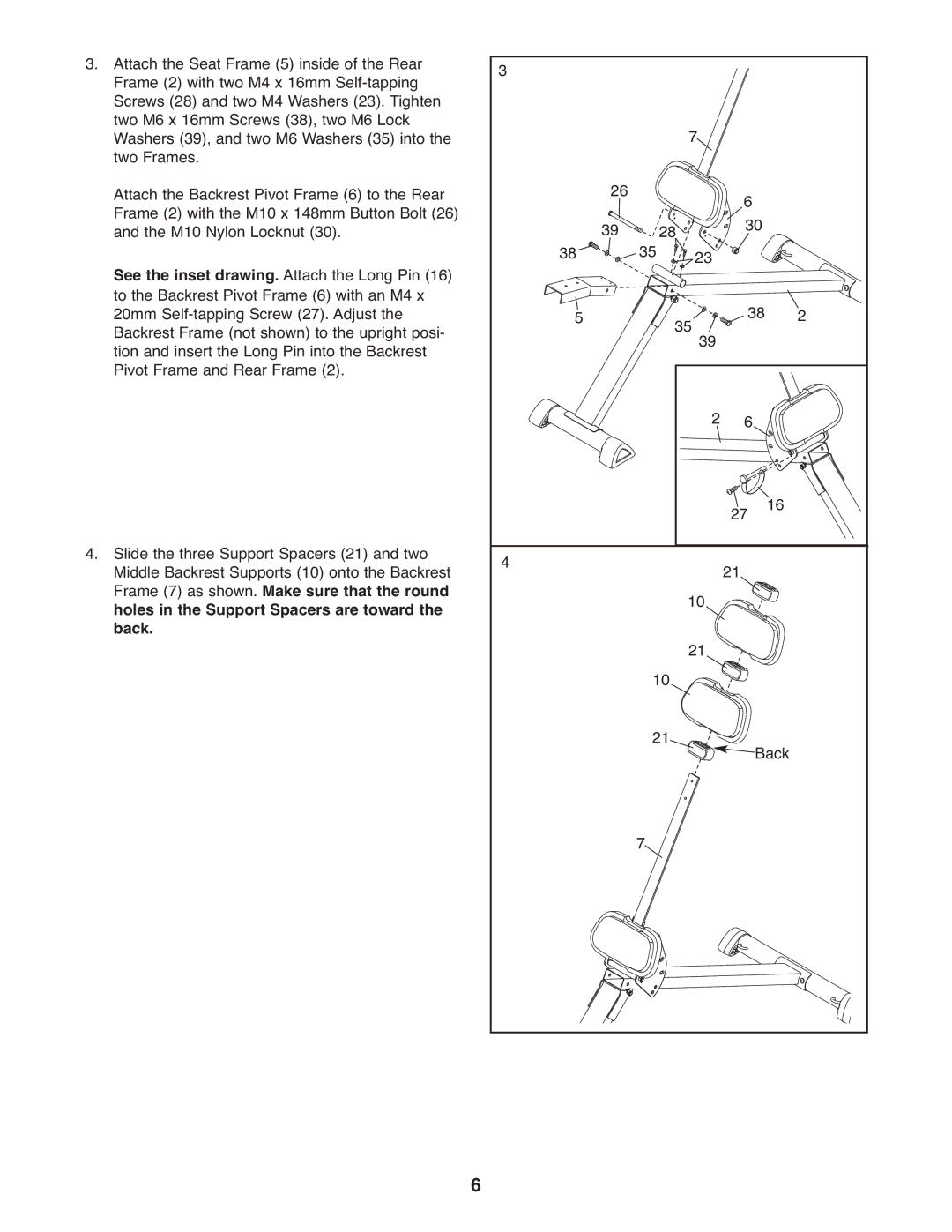
3.Attach the Seat Frame (5) inside of the Rear Frame (2) with two M4 x 16mm
Attach the Backrest Pivot Frame (6) to the Rear Frame (2) with the M10 x 148mm Button Bolt (26) and the M10 Nylon Locknut (30).
See the inset drawing. Attach the Long Pin (16) to the Backrest Pivot Frame (6) with an M4 x 20mm
4.Slide the three Support Spacers (21) and two Middle Backrest Supports (10) onto the Backrest Frame (7) as shown. Make sure that the round holes in the Support Spacers are toward the back.
3 |
|
|
|
|
|
|
|
|
| 7 |
|
| |
| 26 |
|
|
| 6 |
|
38 | 39 | 35 28 | 23 | 30 |
| |
|
|
| ||||
5 |
|
| 35 | 39 | 38 | 2 |
|
|
|
| |||
|
|
|
| 2 | 6 |
|
|
|
|
|
| 27 | 16 |
4 |
|
| 10 | 21 |
| |
|
|
|
|
| ||
|
| 10 | 21 |
|
| |
|
|
|
|
|
| |
|
| 21 |
|
| Back | |
|
|
|
|
| ||
|
| 7 |
|
|
|
|
6
