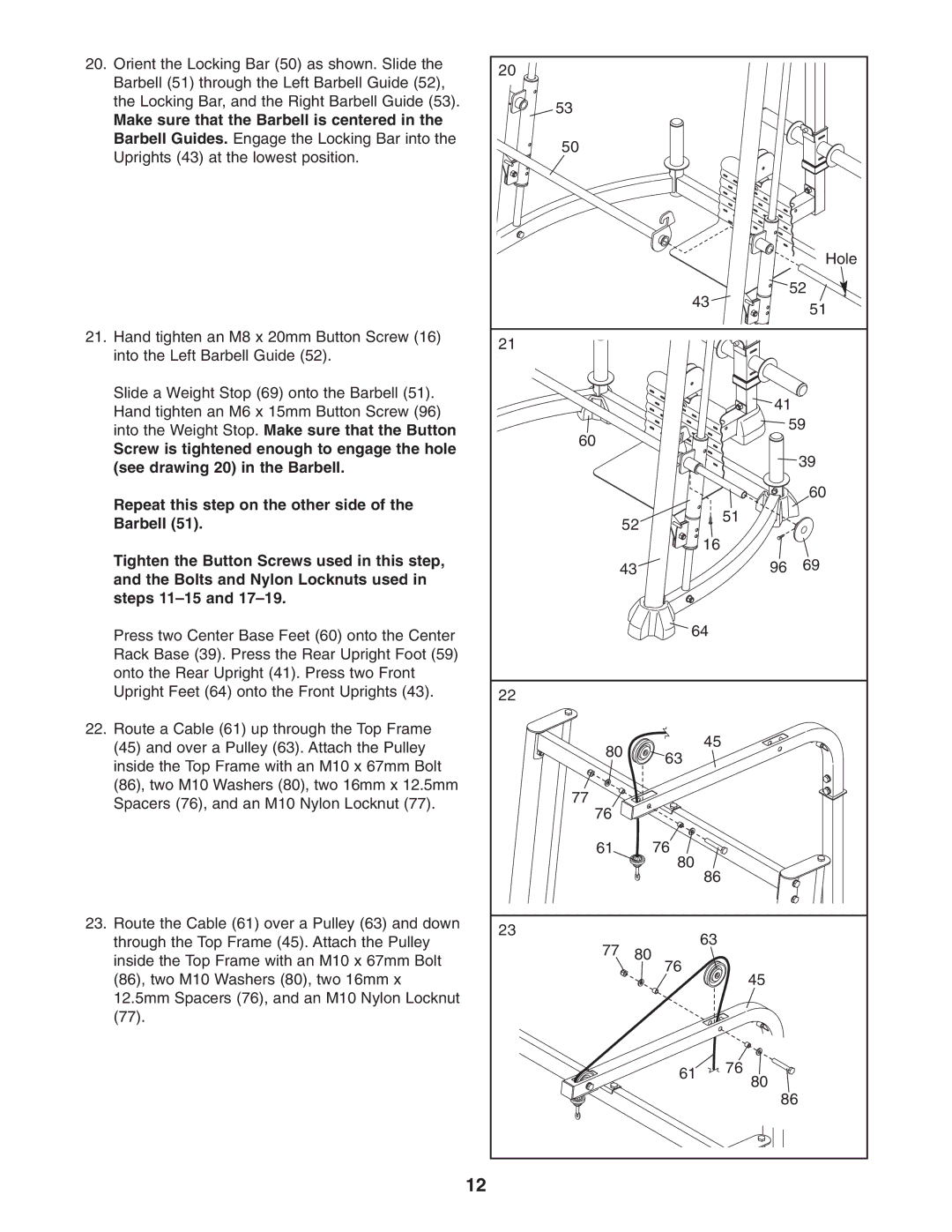
20. Orient the Locking Bar (50) as shown. Slide the | 20 |
|
|
|
|
Barbell (51) through the Left Barbell Guide (52), |
|
|
|
| |
|
|
|
|
| |
the Locking Bar, and the Right Barbell Guide (53). | 53 |
|
|
|
|
Make sure that the Barbell is centered in the |
|
|
|
| |
|
|
|
|
| |
Barbell Guides. Engage the Locking Bar into the | 50 |
|
|
|
|
Uprights (43) at the lowest position. |
|
|
|
| |
|
|
|
|
| |
|
|
|
|
| Hole |
|
|
| 43 |
| 52 |
|
|
|
| 51 | |
|
|
|
|
| |
21. Hand tighten an M8 x 20mm Button Screw (16) | 21 |
|
|
|
|
into the Left Barbell Guide (52). |
|
|
|
| |
|
|
|
|
| |
Slide a Weight Stop (69) onto the Barbell (51). |
|
|
| 41 | |
Hand tighten an M6 x 15mm Button Screw (96) |
|
|
| ||
|
|
|
| 59 | |
into the Weight Stop. Make sure that the Button | 60 |
|
|
| |
|
|
|
| ||
Screw is tightened enough to engage the hole |
|
|
|
| |
|
|
|
| 39 | |
(see drawing 20) in the Barbell. |
|
|
|
| |
|
|
|
|
| |
Repeat this step on the other side of the |
|
|
|
| 60 |
|
|
| 51 |
| |
Barbell (51). |
| 52 |
|
| |
|
|
|
| ||
Tighten the Button Screws used in this step, |
|
| 16 |
|
|
| 43 |
| 96 | 69 | |
and the Bolts and Nylon Locknuts used in |
|
| |||
|
|
|
|
| |
steps |
|
|
|
|
|
Press two Center Base Feet (60) onto the Center |
|
| 64 |
|
|
Rack Base (39). Press the Rear Upright Foot (59) |
|
|
|
|
|
onto the Rear Upright (41). Press two Front |
|
|
|
|
|
Upright Feet (64) onto the Front Uprights (43). | 22 |
|
|
|
|
22. Route a Cable (61) up through the Top Frame |
|
| 45 |
|
|
(45) and over a Pulley (63). Attach the Pulley | 80 |
|
| ||
63 |
|
| |||
inside the Top Frame with an M10 x 67mm Bolt |
|
|
|
| |
|
|
|
|
| |
(86), two M10 Washers (80), two 16mm x 12.5mm | 77 |
|
|
|
|
Spacers (76), and an M10 Nylon Locknut (77). |
|
|
|
| |
76 |
|
|
|
| |
|
|
|
|
| |
| 61 |
| 76 |
|
|
|
|
| 80 |
|
|
|
|
| 86 |
|
|
23. Route the Cable (61) over a Pulley (63) and down | 23 |
| 63 |
|
|
through the Top Frame (45). Attach the Pulley |
|
|
| ||
77 | 80 |
|
| ||
inside the Top Frame with an M10 x 67mm Bolt | 76 |
|
| ||
|
|
|
| ||
(86), two M10 Washers (80), two 16mm x |
|
| 45 |
| |
|
|
|
| ||
12.5mm Spacers (76), and an M10 Nylon Locknut |
|
|
|
|
|
(77). |
|
|
|
|
|
|
|
| 61 | 76 |
|
|
|
| 80 |
| |
|
|
|
|
| |
|
|
|
| 86 | |
| 12 |
|
|
|
|