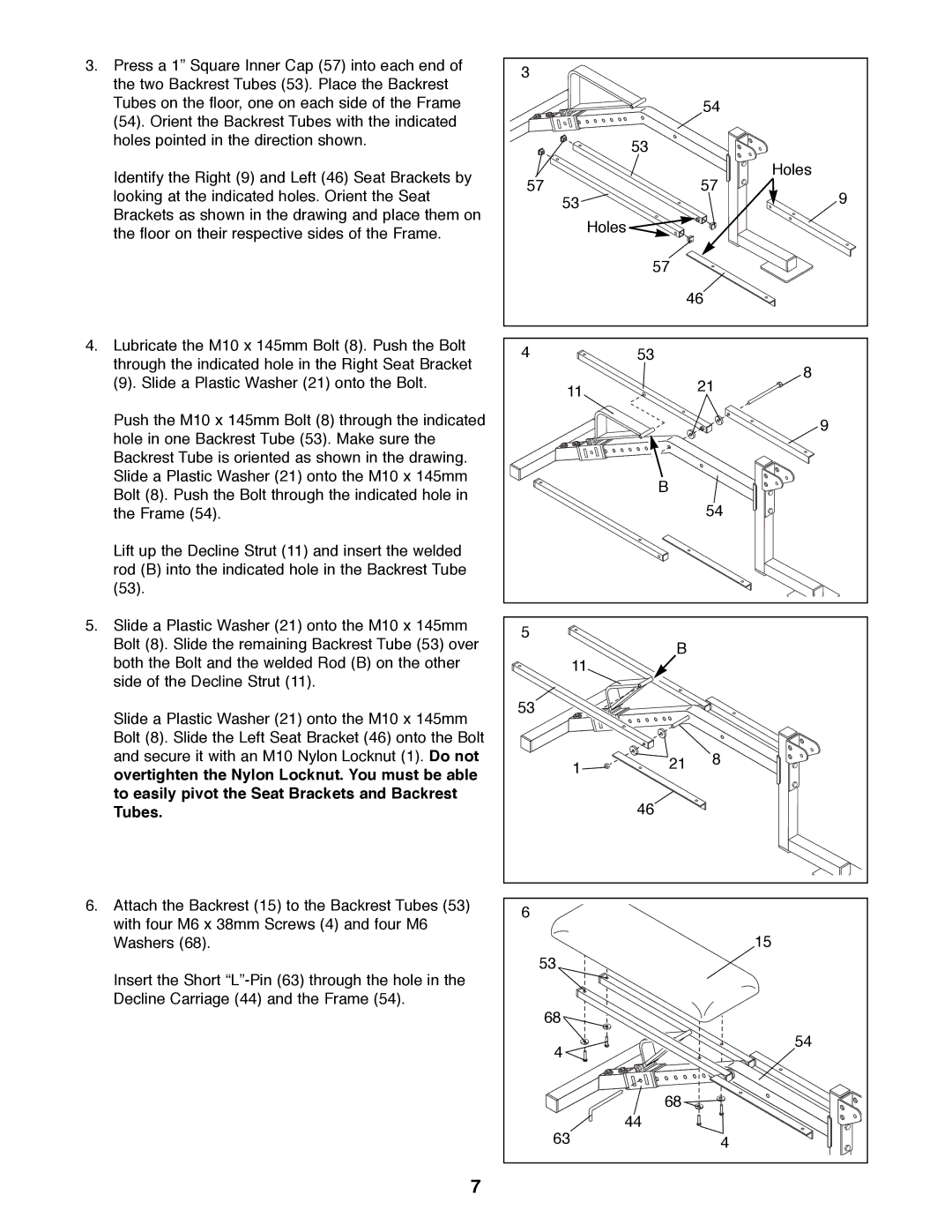
3.Press a 1Ó Square Inner Cap (57) into each end of the two Backrest Tubes (53). Place the Backrest Tubes on the floor, one on each side of the Frame (54). Orient the Backrest Tubes with the indicated holes pointed in the direction shown.
Identify the Right (9) and Left (46) Seat Brackets by looking at the indicated holes. Orient the Seat Brackets as shown in the drawing and place them on the floor on their respective sides of the Frame.
4.Lubricate the M10 x 145mm Bolt (8). Push the Bolt through the indicated hole in the Right Seat Bracket
(9). Slide a Plastic Washer (21) onto the Bolt.
Push the M10 x 145mm Bolt (8) through the indicated hole in one Backrest Tube (53). Make sure the Backrest Tube is oriented as shown in the drawing. Slide a Plastic Washer (21) onto the M10 x 145mm Bolt (8). Push the Bolt through the indicated hole in the Frame (54).
Lift up the Decline Strut (11) and insert the welded rod (B) into the indicated hole in the Backrest Tube (53).
5.Slide a Plastic Washer (21) onto the M10 x 145mm Bolt (8). Slide the remaining Backrest Tube (53) over both the Bolt and the welded Rod (B) on the other side of the Decline Strut (11).
Slide a Plastic Washer (21) onto the M10 x 145mm Bolt (8). Slide the Left Seat Bracket (46) onto the Bolt and secure it with an M10 Nylon Locknut (1). Do not overtighten the Nylon Locknut. You must be able to easily pivot the Seat Brackets and Backrest Tubes.
6.Attach the Backrest (15) to the Backrest Tubes (53) with four M6 x 38mm Screws (4) and four M6 Washers (68).
Insert the Short
3
54
53
Holes
5757
53 | 9 |
Holes ![]()
| 57 |
|
| 46 | |
4 | 53 | 8 |
|
| |
11 |
| 21 |
|
| |
|
| 9 |
| B |
|
|
| 54 |
5 | B |
|
11 |
| |
|
| |
53 |
|
|
1 | 21 | 8 |
|
| |
| 46 |
|
6 |
|
|
|
| 15 |
53 |
|
|
68 |
|
|
4 |
| 54 |
|
| |
| 68 |
|
63 | 44 |
|
| 4 | |
7