PART IDENTIFICATION CHART
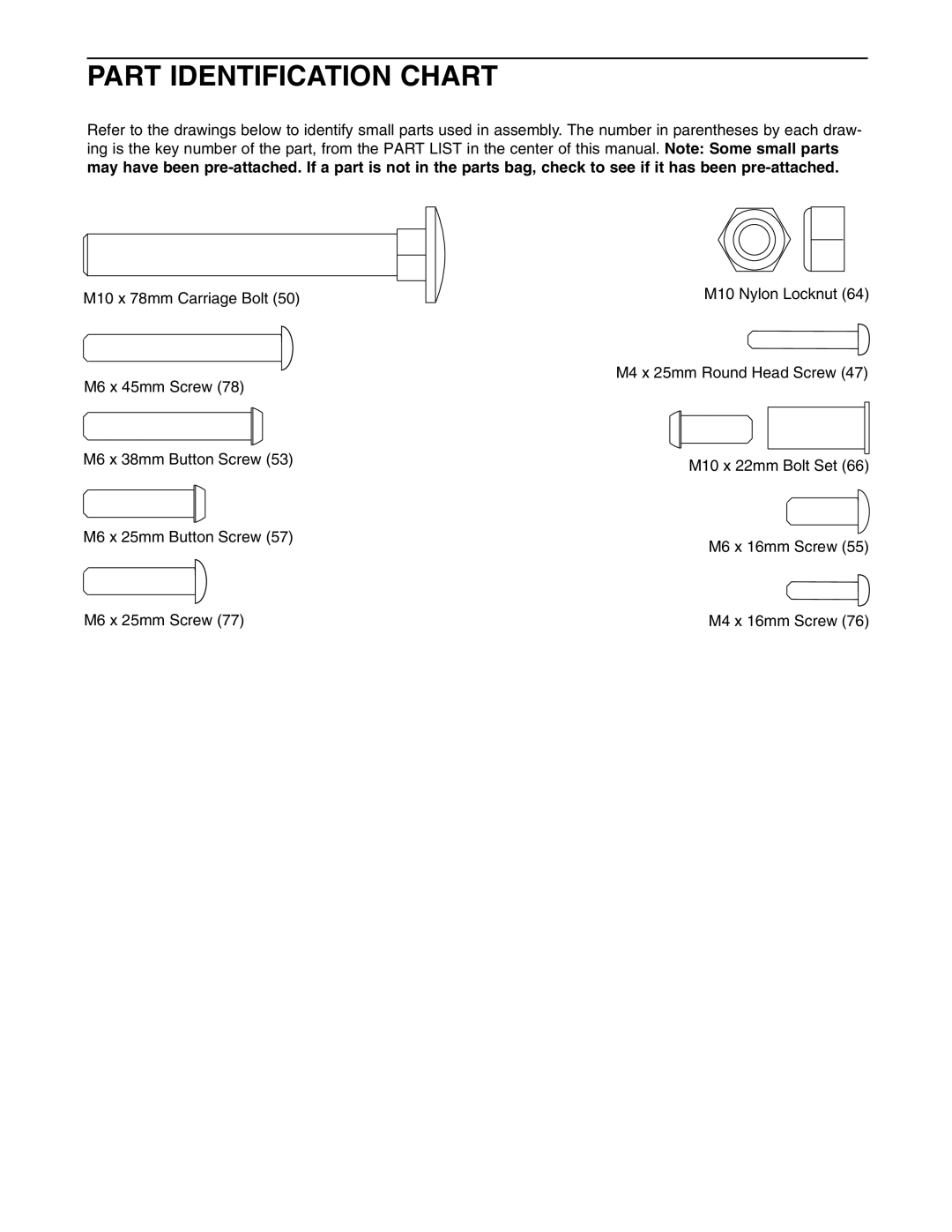
Refer to the drawings below to identify small parts used in assembly. The number in parentheses by each draw- ing is the key number of the part, from the PART LIST in the center of this manual. Note: Some small parts may have been
M10 x 78mm Carriage Bolt (50)
M10 Nylon Locknut (64)
M4 x 25mm Round Head Screw (47)
M6 x 45mm Screw (78)
M6 x 38mm Button Screw (53) | M10 x 22mm Bolt Set (66) |
|
M6 x 25mm Button Screw (57)
M6 x 16mm Screw (55)
M6 x 25mm Screw (77) | M4 x 16mm Screw (76) |