
PFEVEL2486.0 specifications
The ProForm PFEVEL2486.0 is a remarkable piece of fitness equipment designed to enhance your home workout experience. This elliptical machine stands out with its blend of advanced technology, user-friendly features, and durable build quality, making it an excellent choice for individuals of all fitness levels.One of the main features of the ProForm PFEVEL2486.0 is its adjustable incline. Users can change the incline level to target different muscle groups, adding variety to their workouts and helping to maximize calorie burn. With multiple incline options, it allows for a versatile exercise routine that can be easily adapted to meet individual fitness goals.
The elliptical is equipped with a powerful, smooth-motion flywheel that ensures a quiet workout experience. This feature is particularly beneficial for those who may be working out at home and want to avoid disturbing others. The flywheel's weight also contributes to the stability of the machine, allowing for a robust yet smooth motion during use.
In terms of technology, the ProForm PFEVEL2486.0 boasts a large, easy-to-read display that tracks crucial metrics such as time, distance, speed, and calories burned. This console helps users keep track of their progress and motivates them to achieve their fitness objectives. The elliptical also features built-in workout programs that are specifically designed to guide users through effective workouts, catering to various fitness levels and preferences.
Another standout characteristic is the comfort and ergonomic design of the ProForm PFEVEL2486.0. The oversized pedals offer ample space and grip, ensuring a secure footing during intense workouts. Additionally, the machine has built-in handrails that provide support and can be used to monitor your heart rate, thanks to the integrated sensors which allow users to manage their workout intensity effectively.
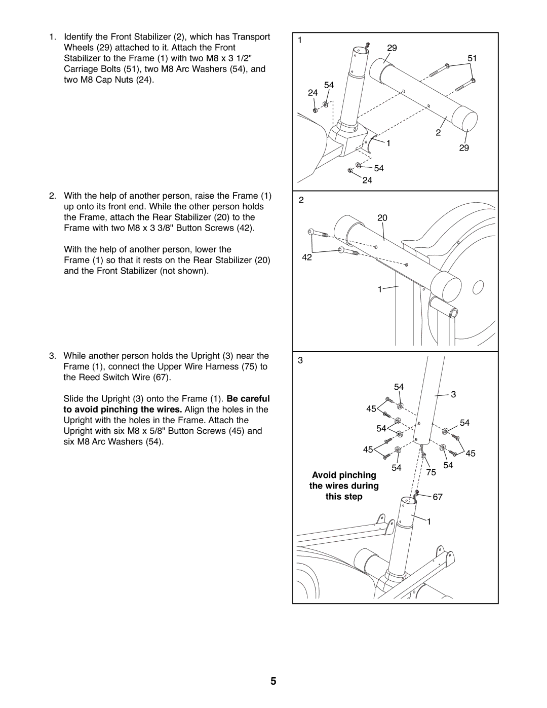
Moreover, the ProForm PFEVEL2486.0 features a space-saving design, making it perfect for home gyms or limited spaces. It can easily be moved around due to its lightweight construction with transport wheels, allowing users to rearrange their workout area with ease.
In summary, the ProForm PFEVEL2486.0 elliptical machine combines advanced technology with user-oriented design features. Its adjustable incline, quiet performance, and comfortable build make it an excellent investment for anyone looking to improve their fitness from the comfort of home.