HOW TO ADJUST THE REED SWITCH | HOW TO ADJUST THE DRIVE BELT |
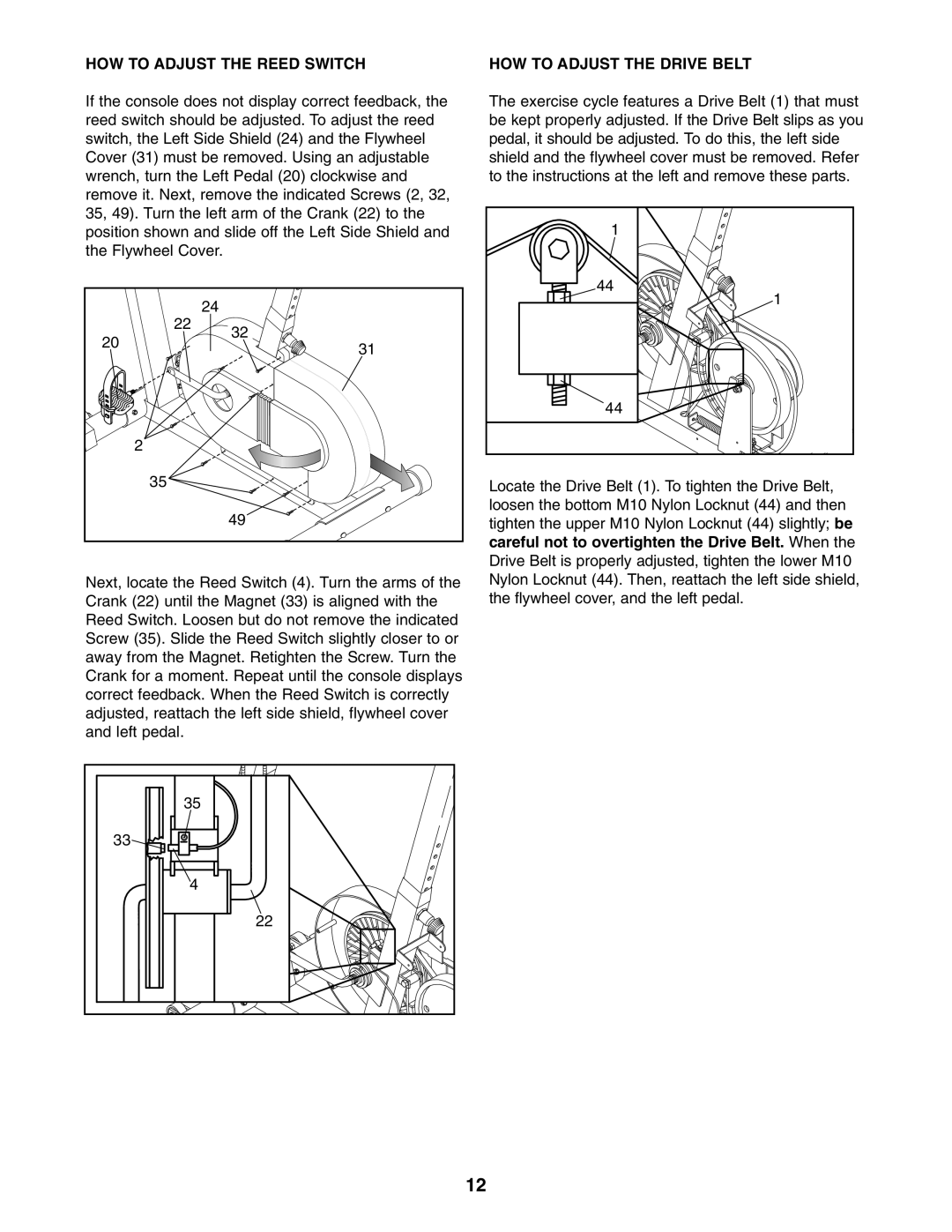
If the console does not display correct feedback, the | The exercise cycle features a Drive Belt (1) that must | |
reed switch should be adjusted. To adjust the reed | be kept properly adjusted. If the Drive Belt slips as you | |
switch, the Left Side Shield (24) and the Flywheel | pedal, it should be adjusted. To do this, the left side | |
Cover (31) must be removed. Using an adjustable | shield and the flywheel cover must be removed. Refer | |
wrench, turn the Left Pedal (20) clockwise and | to the instructions at the left and remove these parts. | |
remove it. Next, remove the indicated Screws (2, 32, |
| |
35, 49). Turn the left arm of the Crank (22) to the | 1 | |
position shown and slide off the Left Side Shield and | ||
the Flywheel Cover. |
|
|
|
| 44 |
24 |
| 1 |
|
| |
22 | 32 |
|
20 |
| |
31 |
| |
|
| |
|
| 44 |
2 |
|
|
35 |
| Locate the Drive Belt (1). To tighten the Drive Belt, |
| 49 | loosen the bottom M10 Nylon Locknut (44) and then |
| tighten the upper M10 Nylon Locknut (44) slightly; be | |
|
| careful not to overtighten the Drive Belt. When the |
|
| Drive Belt is properly adjusted, tighten the lower M10 |
Next, locate the Reed Switch (4). Turn the arms of the | Nylon Locknut (44). Then, reattach the left side shield, | |
Crank (22) until the Magnet (33) is aligned with the | the flywheel cover, and the left pedal. | |
Reed Switch. Loosen but do not remove the indicated |
| |
Screw (35). Slide the Reed Switch slightly closer to or |
| |
away from the Magnet. Retighten the Screw. Turn the |
| |
Crank for a moment. Repeat until the console displays |
| |
correct feedback. When the Reed Switch is correctly |
| |
adjusted, reattach the left side shield, flywheel cover |
| |
and left pedal. |
|
|
35 |
33 |
4 |
22 |
12