ASSEMBLY
Assembly requires two persons. Set the treadmill in a cleared area and remove all packing materials. Do not dis- pose of the packing materials until assembly is completed. Note: The underside of the treadmill walking belt is coated with
Assembly requires the included allen wrench ![]() and your own phillips screwdriver
and your own phillips screwdriver ![]()
![]() and
and
adjustable wrench ![]() . For help identifying assembly hardware, see the drawings below.
. For help identifying assembly hardware, see the drawings below.
|
| Shock Nutt | 3/4”Tekk Screw | |
5/16” Star | 3/8” Star | Wheell Nut | ||
Washer | Washer | |||
Washer | Washer |
| ||
Shock Bolt |
| Latch Screw | ||
|
| |||
|
| Console Bolt | 2” Screw | |
|
|
| ||
Upright Bolt |
| Wheel Bolt | ||
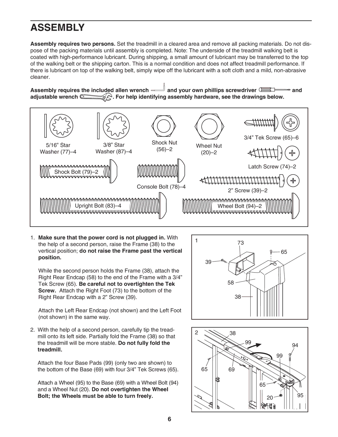
1.Make sure that the power cord is not plugged in. With the help of a second person, raise the Frame (38) to the vertical position; do not raise the Frame past the vertical position.
While the second person holds the Frame (38), attach the Right Rear Endcap (58) to the end of the Frame with a 3/4” Tek Screw (65). Be careful not to overtighten the Tek Screw. Attach the Right Foot (73) to the bottom of the Right Rear Endcap with a 2” Screw (39).
Attach the Left Rear Endcap (not shown) and the Left Foot (not shown) in the same way.
2.With the help of a second person, carefully tip the tread- mill onto its left side. Partially fold the Frame (38) so that the treadmill will be more stable. Do not fully fold the treadmill.
Attach the four Base Pads (99) (only two are shown) to the bottom of the Base (69) with four 3/4” Tek Screws (65).
Attach a Wheel (95) to the Base (69) with a Wheel Bolt (94) and a Wheel Nut (20). Do not overtighten the Wheel
Bolt; the Wheels must be able to turn freely.
173
![]() 65
65
39 ![]()
![]()
![]()
![]()
58 ![]()
38
2 | 38 |
|
|
| 99 |
| 94 |
|
|
| |
|
|
| 99 |
65 | 69 |
|
|
|
| 65 |
|
|
| 20 | 95 |
|
|
|
6