Trane Custom Climate Changer Air Handlers manual TCP Base Section Assembly Typical, Installation

Models: CAH-SVX01A-EN Custom Climate Changer Air Handlers

1 60
Download 60 pages 9 Kb
Page 13
Image 13
TCP Base Section

TCP Base Section

Assembly (Typical)

Note: Failure to completely compress the gasketing may result in air leakage.

1Join the two units and secure with field provided 5/8-inch flat washers and 5/8-inch X 2-1/2-inch grade 9 bolts though each of the six holes.

2Caulk the overlapping flange along the length of each split to maintain a seal.

Note: Use a polyurethane or equivalent caulk.

Installation

3Apply the 3-inch X 1/8-inch gasket evenly across the two joined edges of the splits.

4Before installing the pre-cut 4- inch 18 gauge joining strip over the gasket, pre-drill holes in the floor using the 4-inch strip as a guide with a 7/32-inch drill bit at 12 inch centers.

5Apply the 4-inch joining strip over the gasket and uniformly straddle the splits. Secure with number 14 sheet-metal screws at 12-inch centers.

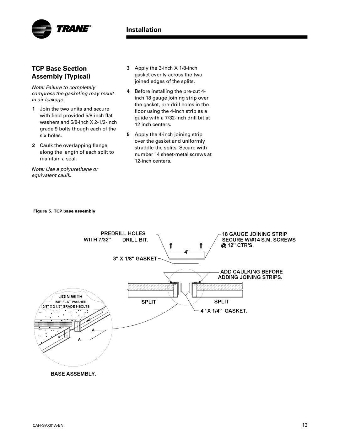
Figure 5. TCP base assembly

PREDRILL HOLES

18 GAUGE JOINING STRIP

WITH 7/32"

DRILL BIT.

SECURE W/#14 S.M. SCREWS


@ 12" CTR'S.


3" X 1/8" GASKET

4"


JOIN WITH

5/8" FLAT WASHER 5/8" X 2 1/2" GRADE 9 BOLTS

A

A

ADD CAULKING BEFORE

ADDING JOINING STRIPS.

SPLIT

SPLIT


4" X 1/4" GASKET.

BASE ASSEMBLY.

CAH-SVX01A-EN

13

Page 13
Image 13
Trane Custom Climate Changer Air Handlers, CAH-SVX01A-EN manual TCP Base Section Assembly Typical, Installation