Installation
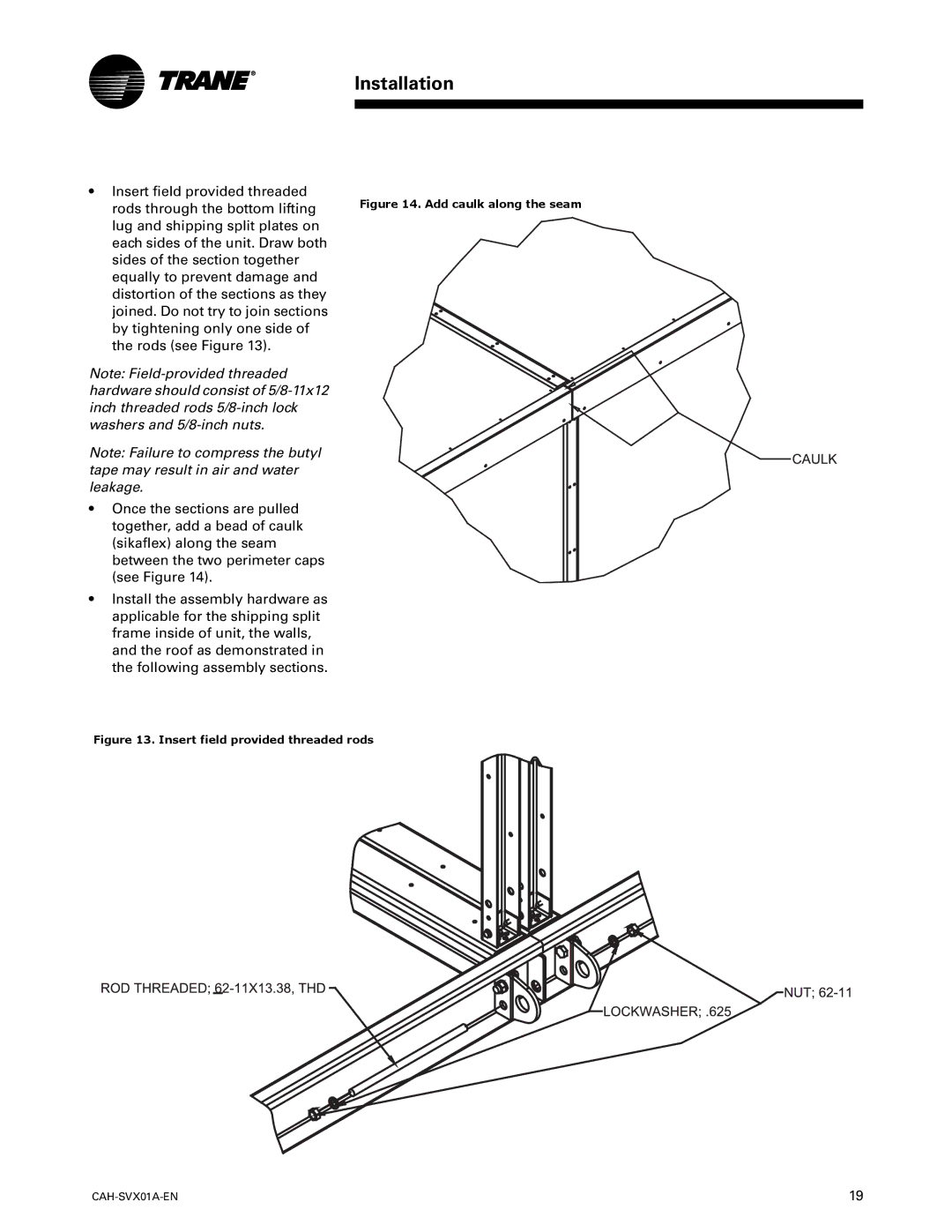
•Insert field provided threaded rods through the bottom lifting lug and shipping split plates on each sides of the unit. Draw both sides of the section together equally to prevent damage and distortion of the sections as they joined. Do not try to join sections by tightening only one side of the rods (see Figure 13).
Note:
Note: Failure to compress the butyl tape may result in air and water leakage.
•Once the sections are pulled together, add a bead of caulk (sikaflex) along the seam between the two perimeter caps (see Figure 14).
•Install the assembly hardware as applicable for the shipping split frame inside of unit, the walls, and the roof as demonstrated in the following assembly sections.
Figure 14. Add caulk along the seam
Figure 13. Insert field provided threaded rods
| 19 |