Trane Custom Climate Changer Air Handlers manual Installation, 7Pitch the suction line slightly

Models: CAH-SVX01A-EN Custom Climate Changer Air Handlers

1 60
Download 60 pages 9 Kb
Page 37
Image 37
Manual background

Installation

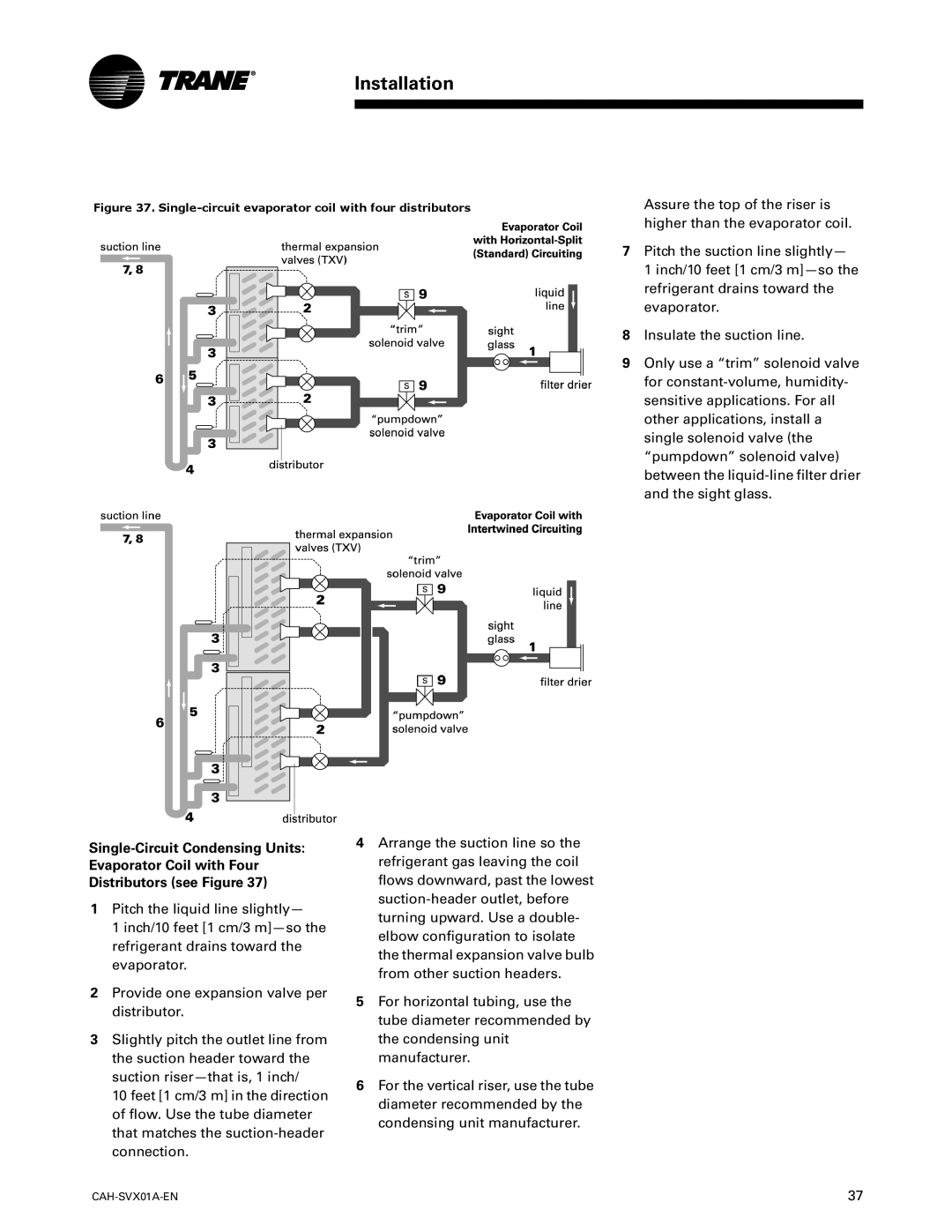
Figure 37. Single-circuit evaporator coil with four distributors

Assure the top of the riser is higher than the evaporator coil.

7Pitch the suction line slightly—

1 inch/10 feet [1 cm/3 m]—so the refrigerant drains toward the evaporator.

8Insulate the suction line.

9Only use a “trim” solenoid valve for constant-volume, humidity- sensitive applications. For all other applications, install a single solenoid valve (the “pumpdown” solenoid valve) between the liquid-line filter drier and the sight glass.

Single-Circuit Condensing Units: Evaporator Coil with Four Distributors (see Figure 37)

1Pitch the liquid line slightly—

1 inch/10 feet [1 cm/3 m]—so the refrigerant drains toward the evaporator.

2Provide one expansion valve per distributor.

3Slightly pitch the outlet line from the suction header toward the suction riser—that is, 1 inch/

10 feet [1 cm/3 m] in the direction of flow. Use the tube diameter that matches the suction-header connection.

CAH-SVX01A-EN

4Arrange the suction line so the refrigerant gas leaving the coil flows downward, past the lowest suction-header outlet, before turning upward. Use a double- elbow configuration to isolate the thermal expansion valve bulb from other suction headers.

5For horizontal tubing, use the tube diameter recommended by the condensing unit manufacturer.

6For the vertical riser, use the tube diameter recommended by the condensing unit manufacturer.

37

Page 37
Image 37
Trane Custom Climate Changer Air Handlers, CAH-SVX01A-EN manual Installation, 7Pitch the suction line slightly